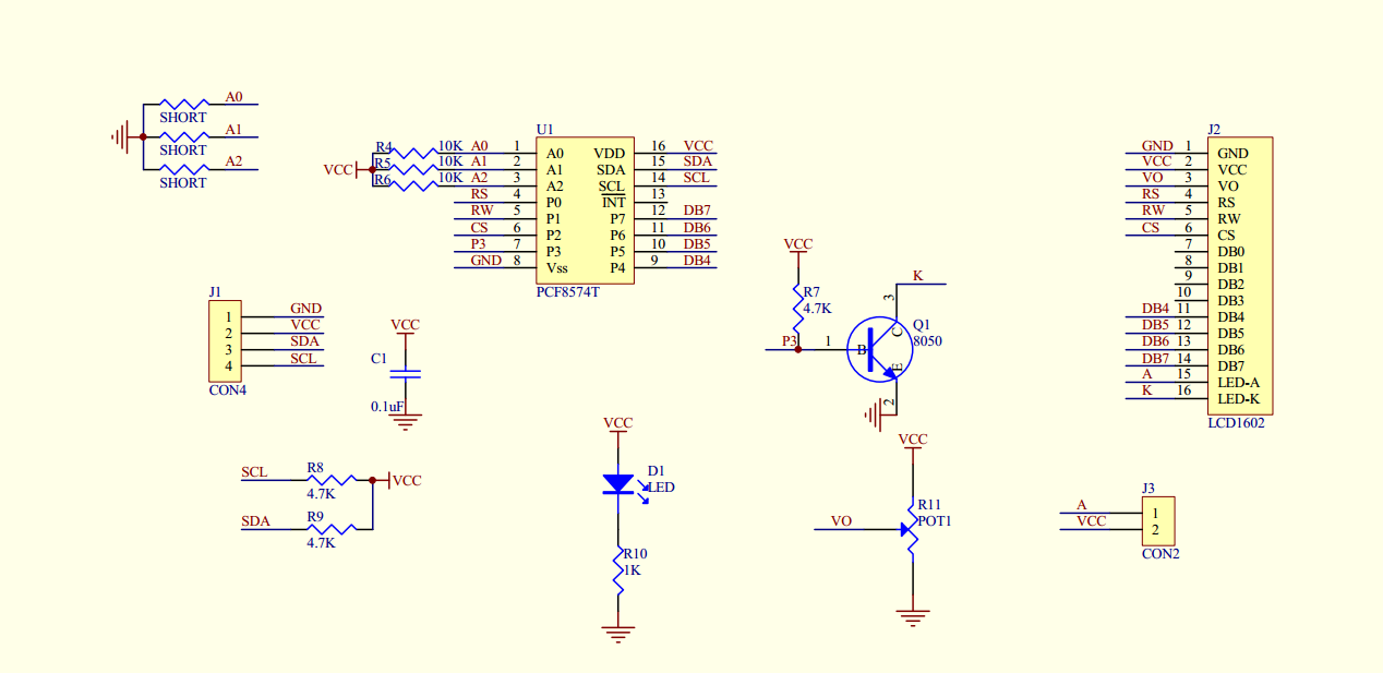
This This 1602 LCD display screen can display 16(each row) x 2 (rows) characters. Generally, LCD 1602 has parallel port, it occupy many GPIO pins. This 1602 LCD comes with a I2C communicate interface using a PCF8574 IC Chip. It means you can realize data display via only 2 wires.
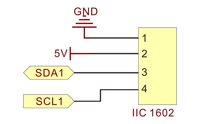
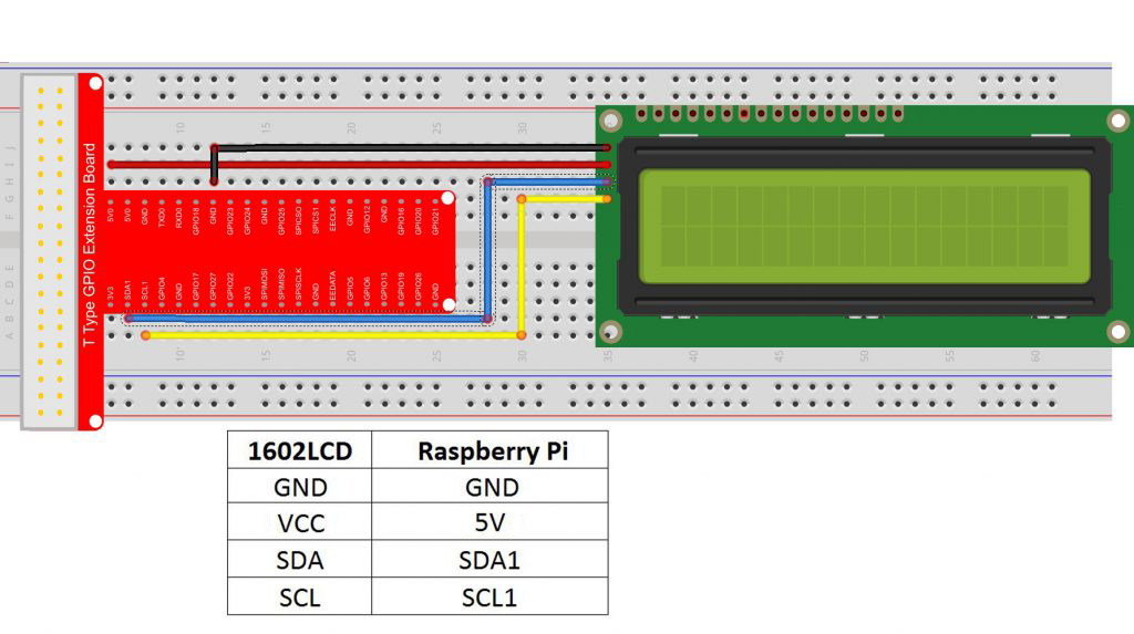
Wiring up IIC 1602 LCD to Pi as following connection graph.
Note: SDA 1 is BCM 2 , SCL 1 is BCM 3 , for detail about GPIO#, read Lesson 2 , these 2 pins normally are used to exchange serial data with external devices.
Hardware Setup:
Sample code
To use the IIC 1602 LCD,we should enable the I2C port firstly, please follow the steps as followed:
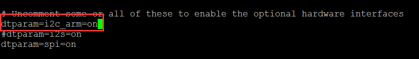
1) Open IIC
sudo nano /boot/config.txt
open the file /boot/config.txt, find the code line”dtparam=i2c_arm”,checking if there is # sign in front of the line, uncomment it (remove the # in front of this line), and make sure the end of the line is”on”, finally the code should look like this:
Press Ctrl+X,and type “Y” to save the file you revised.
2) Load Modules
sudo nano /etc/modules
open /etc/modules file,Add these two lines as below:
i2c-bcm2708
i2c-dev
Press Ctrl+X, and type “Y” to save the file you revised.
3) Install i2c python library and smbus
sudo apt-get install -y python-smbus i2c-tools
Now reboot Pi
reboot
4) Cheking the if library is installed successfully by typing following command:
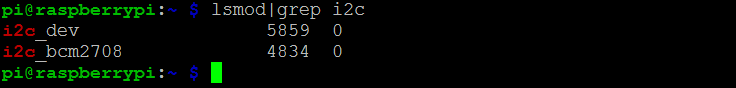
lsmod | grep i2c
If the terminal will show the message as below if installed successfully,otherwise please repeat above steps.
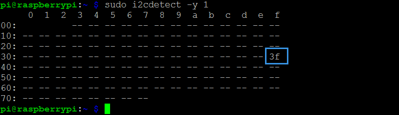
5) Checking for any components connected to the i2c bus by using i2c detect
sudo i2cdetect -y 1 or port 0 on the older Raspberry Pi sudo i2cdetect -y 0
Once run the command, A table like below will be shown and if any devices are connected, the address will be shown. Below you can see that a device is connected to the i2c bus which is using the address of 0x3f.
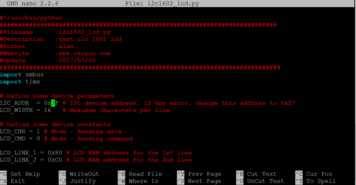
Note: Above code line 5 is to define LCD I2C address. If your LCD does not display properly, you might need change the value from 0x3f to 0x27
For C language user,please take the steps as followed:
1) Download the sample code by typing following terminal command:
If you want to customize the sample code file , you can use nano editor to edit source code by typing following command in terminal:
sudo nano i2c1602_lcd.c
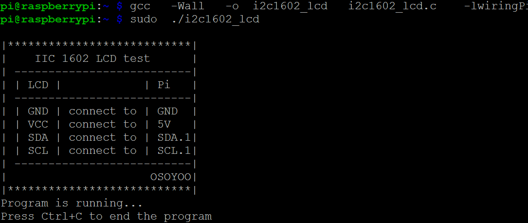
2) copmlie code
gcc -Wall -o i2c1602_lcd i2c1602_lcd.c -lwiringPi
3) Run the program
sudo ./i2c1602_lcd
4) Running result
Once run the program, the terminal will message as code, while the LCD screen will display the message at the same time.
Note:You can adjust the contrast of the screen by spinning the potentiometer screw in the back of the LCD clockwise or anticlockwise, until the screen displays characters clearly.
C source code and comments:
#include < stdio.h>
#include < wiringPi.h>
#include < wiringPiI2C.h>
#include < string.h>
int LCDAddr = 0x3f;//I2c address of LCD, some LCD i2c address might be 0x27
int BLEN = 0;//1--open backlight.0--close backlight
int fd;//linux file descriptor
//send an  16 bits data to LCD buffer
void write_word(int data){
    int temp = data;
    if ( BLEN == 1 )
        temp |= 0x08;
    else
        temp &= 0xF7;
    wiringPiI2CWrite(fd, temp);
}
//send control command to lcd
void send_command(int comm){
    int buf;
    // Send bit7-4 firstly
    buf = comm & 0xF0;
    buf |= 0x04;            // RS = 0, RW = 0, EN = 1
    write_word(buf);
    delay(2);
    buf &= 0xFB;            // Make EN = 0
    write_word(buf);
    // Send bit3-0 secondly
    buf = (comm & 0x0F)
    buf |= 0x04;            // RS = 0, RW = 0, EN = 1
    write_word(buf);
    delay(2);
    buf &= 0xFB;            // Make EN = 0
    write_word(buf);
}
//send character to lcd
void send_data(int data){
    int buf;
    // Send bit7-4 firstly
    buf = data & 0xF0;
    buf |= 0x05;            // RS = 1, RW = 0, EN = 1
    write_word(buf);
    delay(2);
    buf &= 0xFB;            // Make EN = 0
    write_word(buf);
    // Send bit3-0 secondly
    buf = (data & 0x0F)
    buf |= 0x05;            // RS = 1, RW = 0, EN = 1
    write_word(buf);
    delay(2);
    buf &= 0xFB;            // Make EN = 0
    write_word(buf);
}
//initialize the lcd
void init(){
    send_command(0x33); // Must initialize to 8-line mode at first
    delay(5);
    send_command(0x32); // Then initialize to 4-line mode
    delay(5);
    send_command(0x28); // 2 Lines & 5*7 dots
    delay(5);
    send_command(0x0C); // Enable display without cursor
    delay(5);
    send_command(0x01); // Clear Screen
    wiringPiI2CWrite(fd, 0x08);
}
//clear screen
void clear(){
    send_command(0x01); //clear Screen
}
//Print the message on the lcd
void write(int x, int y, char data[]){
    int addr, i;
    int tmp;
    if (x < 0) x = 0; if (x > 15) x = 15;
    if (y < 0) y = 0; if (y > 1)  y = 1;
    // Move cursor
    addr = 0x80 + 0x40 * y + x;
    send_command(addr);

    tmp = strlen(data);
    for (i = 0; i < tmp; i++){
        send_data(data[i]);
    }
}
void print_info()
{
    printf("\n");
    printf("|***************************|\n");
    printf("|    IIC 1602 LCD test      |\n");
    printf("| --------------------------|\n");
    printf("| | LCD |            | Pi   |\n");
    printf("| --------------------------|\n");
    printf("| | GND | connect to | GND  |\n");
    printf("| | VCC | connect to | 5V   |\n");
    printf("| | SDA | connect to | SDA.1|\n");
    printf("| | SCL | connect to | SCL.1|\n");
    printf("| --------------------------|\n");
    printf("|                     OSOYOO|\n");
    printf("|***************************|\n");
    printf("Program is running...\n");
    printf("Press Ctrl+C to end the program\n");
}
int main(){
    //init I2C, assign a buffer handler to variable fd
    fd = wiringPiI2CSetup(LCDAddr);
    init();
    print_info();
    write(0, 0, "Hi man.Welcome ");
    write(0, 1, "to osoyoo.com");
    delay(3000);
    clear();
    while(1){
        write(0,0,"This is Lesson13");
        write(0,1,"IIC LCD Test");
        delay(1000);
    }
    return 0;
}
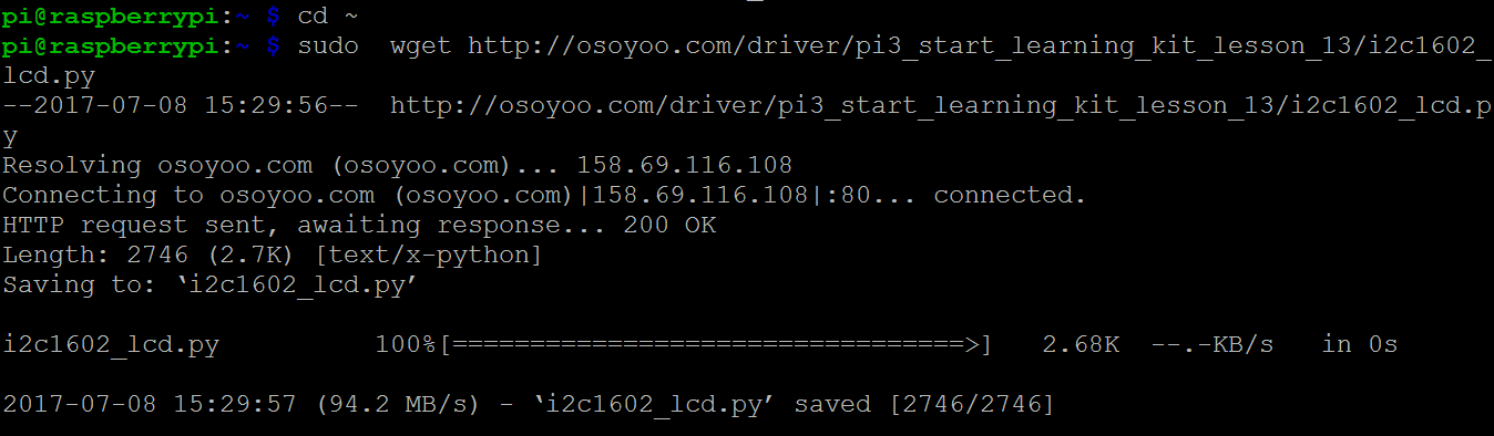
For Python language user
1) Download the Python code from osoyoo by typing following commands:
In C language code, Line 6:
“int BLEN = 0;//1–open backlight.0–close backlight”
In Python code,
“LCD_BACKLIGHT = 0x08 # On
#LCD_BACKLIGHT = 0x00 # Off”
Please change “0x08” to “0x00”


The LCD backlight consumes quite a lot of power. Whats the function to turn off the backlight?
You can turn around the Potentiometer at the back of LCD to adjust LCD backlight
Thats for adjusting contrast. am talking about turning the backlight off from code.
In C language code, Line 6:
“int BLEN = 0;//1–open backlight.0–close backlight”
In Python code,
“LCD_BACKLIGHT = 0x08 # On
#LCD_BACKLIGHT = 0x00 # Off”
Please change “0x08” to “0x00”