Content
- Introduction
- Preparations
- About HC-06 Bluetooth Module
- Examples
Introduction
Bluetooth is a telecommunications industry specification that describes how mobile devices, computers and other devices can easily communicate with each other using a short-range wireless connection.
In this lesson, we will show what is HC-06 bluetooth module and how to setup communications between an Arduino and a Bluetooth device running serial terminal software – in this case an Android smartphone. Please note that the Bluetooth module used in this tutorial is not compatible with iOS devices.
Preparations
Hardware
- Osoyoo UNO Board (Fully compatible with Arduino UNO rev.3) x 1
- HC-06 Bluetooth Module x 1
- Android smartphone x 1
- Breadboard x 1
- Jumpers
- USB Cable x 1
- PC x 1
Software
- Arduino IDE (version 1.6.4+)
About HC-06 Bluetooth Module
What is Bluetooth ?

Bluetooth is a wireless technology standard for exchanging data over short distances (using short-wavelength UHF radio waves in the ISM band from 2.4 to 2.485 GHz) from fixed and mobile devices, and building personal area networks (PANs). Range is approximately 10 Meters (30 feet).
What is HC-06 Bluetooth Module?
The HC-06 is a class 2 slave Bluetooth module designed for transparent wireless serial communication. Once it is paired to a master Bluetooth device such as PC, smart phones and tablet, its operation becomes transparent to the user. All data received through the serial input is immediately transmitted over the air. When the module receives wireless data, it is sent out through the serial interface exactly at it is received. No user code specific to the Bluetooth module is needed at all in the user microcontroller program.
The module has two modes of operation, Command Mode where we can send AT commands to it and Data Mode where it transmits and receives data to and from another Bluetooth module. By default the device was in Command mode and needs to pair with some device to get it into data mode.
Features:
- Bluetooth v2.0+EDR
- 2.4GHz ISM band frequency
- Default baudrate: 9600
- Power supply: 3.6V to 6V DC
- Passkey: 1234
The HC-06 will work with supply voltage of 3.6VDC to 6VDC, however, the logic level of RXD pin is 3.3V and is not 5V tolerant. It can be damaged if connect directly to a 5V device (e.g Arduino Uno and Mega). A Logic Level Converter is recommended to protect the HC-06.
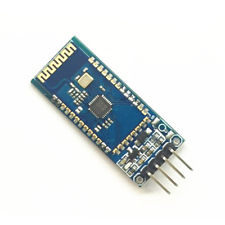
Pin Definitions
Board needs 4-lines to communicate most of the times, i.e Vcc, Gnd, RX and TX pin. There are two additional pin onboard, one is STATE pin and the other is EN pin, this Reset pin can be used to send reset signal from microcontroller to reset the bluetooth module. Refer the table and image below in detail:
| Pin |
Description |
| VCC |
Supply input 3.3V to 5.5V Input |
| GND |
Ground |
| TXD |
Transmit Data (Connect RX line from other peripheral here) |
| RXD |
Receive Data (Connect TX line from other peripheral here) |
Notice that we used the SoftwareSerial library to enable two digital pins to act as a virtual serial port. This was done in order to free up the hardware TX/RX pins. Why? If you connect the Bluetooth module to TX/RX – you will have difficulty upload a sketch via USB.
When the power is on, the Bluetooth LED light flashes constantly, meaning there is no connection.
When the equipment is connected, it will become bright.
How does it work?
HC-06 works on serial communication. The Android app is designed to send serial data to the Arduino Bluetooth module when a button is pressed on the app. The Arduino Bluetooth module at other end receives the data and sends it to the Arduino through the TX pin of the Bluetooth module(connected to RX pin of Arduino). The code uploaded to the Arduino checks the received data and compares it. You can open the serial monitor and watch the received data while connecting.
Differences between HC-06 and HC-05
The HC-05 has the ‘full’ firmware on it: many AT commands, and can be both master and slave module. The HC-06 firmware on the other hand only can be a slave device, with very limited AT commands.
Or in other words:
- The HC-05 module can build a connection to other modules. E.g. a Robot being a master and connecting to slave bluetooth module. Or in slave mode to make a wireless bridge to a notebook.
- The HC-06 module only can be a slave. This makes it only useful for say connecting a notebook as a master to a robot with a slave module e.g. for a wireless serial bridge.
For most use cases the HC-06 is enough, as typically I want to have a wireless UART connection to my devices from my notebook.
Configuring HC-06 Using AT Commands
- Test communication
Send: AT (please send it every second)
Back: OK
- Reset the Bluetooth serial baud rate
Send: AT+BAUD1
Back: OK1200
Send: AT+BAUD2
Back: OK2400
……
1———1200
2———2400
3———4800
4———9600 (default)
5———19200
6———38400
7———57600
8———115200
A———460800
B———921600
C———1382400
PC can’t support the baud rate lager than 115200. The solution is: make the MCU have higher baud rate (lager than 115200) through programming, and reset the baud rate to low level through the AT command.
The baud rate reset by the AT command can be kept for the next time even though the power is cut off.
- Reset the Bluetooth name
Send: AT+NAMEname
Back: OKname
- Change Bluetooth Module Pair Password/Pin
Sent : AT+PINxxxx
receive : OKsetpin
(xxxx is the pin code you set)
Pin code can be save even power down.
Example:
Send: AT+PIN1111
Back: OKsetpin
By this step password is changed to 1111, whereas the default is 1234.
This parameter can be kept even though the power is cut off.
Note: More AT Commands can be easily found in the datasheet.
Examples
Using the Android phone and the HC-06 Bluetooth module to turn on/off the Arduino on-board LED
In this example, we will show how to use an Android phone to control the on-board LED of an Arduino via bluetooth protocol.
First of all, we need to install the Amarino app on the smartphone, Amarino is a toolkit to connect Android-driven mobile devices with Arduino microcontrollers via Bluetooth. The toolkit provides easy access to internal phone events which can be further processed on the Arduino open-source prototyping platform, you can also get more info about this app from their official page.
Connection
| Osoyoo UNO |
HC-06 |
| 3.3V |
VCC |
| GND |
GND |
| D10/Software RX |
TXD |
| D11/Software TX |
RXD |
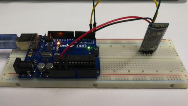
Overhere we use the Software serial port of the Arduino, connect them as below fritzing:

Code Program
After above operations are completed, connect the Arduino board to your computer using the USB cable. The green power LED (labelled PWR) should go on.Open the Arduino IDE and choose corresponding board type and port type for you project. Then load up the following sketch onto your Arduino.
#include <SoftwareSerial.h>// import the serial library
SoftwareSerial mySerial(10, 11); // RX, TX
int ledpin=13; // led on D13 will show blink on / off
int BluetoothData; // the data given from Computer
void setup() {
Serial.begin(4800);
Serial.println("Type AT commands!"); // put your setup code here, to run once:
mySerial.begin(9600);
Serial.println("Bluetooth On please press 1 or 0 blink LED ..");
pinMode(ledpin,OUTPUT);
}
// put your main code here, to run repeatedly:
if (mySerial.available()) {
BluetoothData=mySerial.read();
if(BluetoothData==‘1’) { // if number 1 pressed ….
digitalWrite(ledpin,1);
Serial.println(“LED On D13 ON ! “);
}
if (BluetoothData==‘0’) { // if number 0 pressed ….
digitalWrite(ledpin,0);
Serial.println(“LED On D13 Off ! “);
}
}
delay(100);// prepare for next data …
}
Install and config the Amrion App
Open the App and it will search for this Bluetooth module,
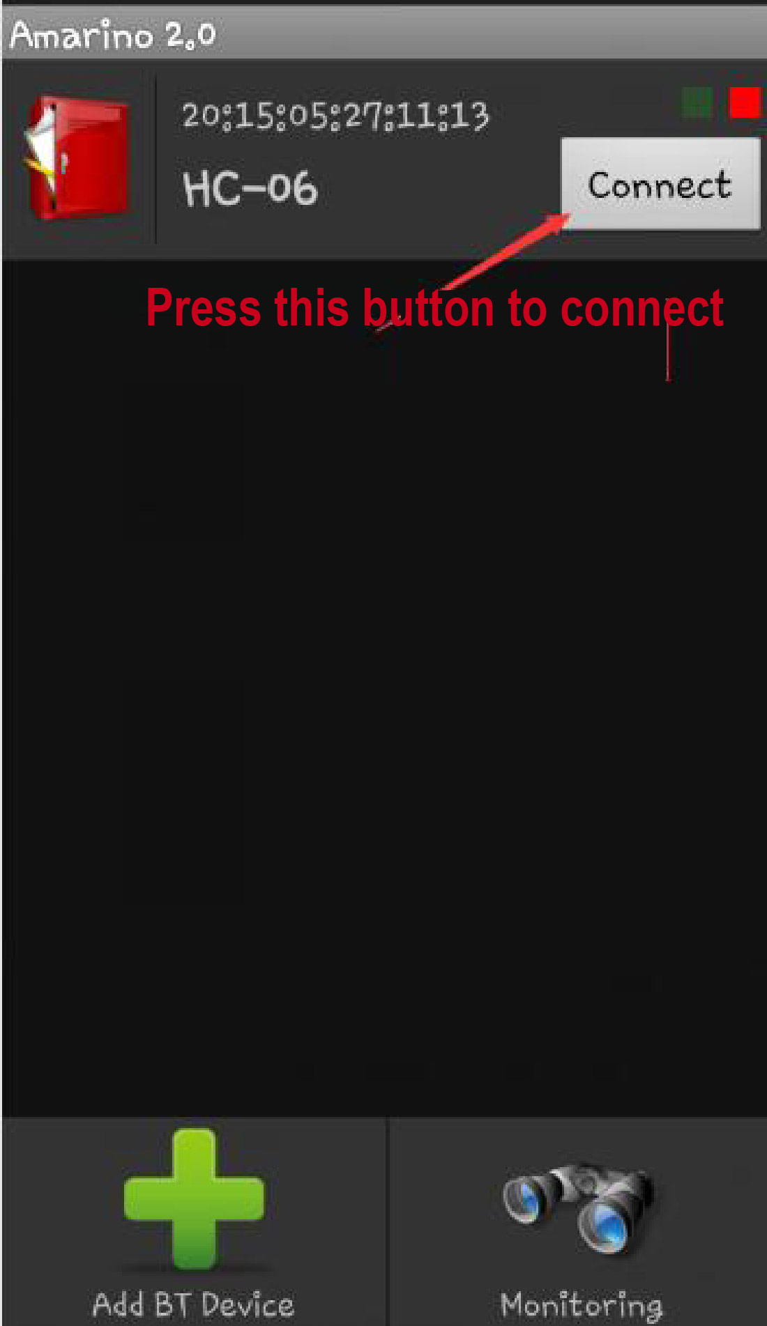
When the connection will be prompted for pairing, input 1234 to the column, if not, you can try 0000,
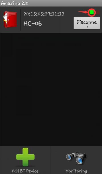
As above photo, the green box is lit to indicate the connection is successful. At the same time, the LED light of Bluetooth module has become bright all the time.
Then click the Monitoring button in the lower right, and enter the following interface:
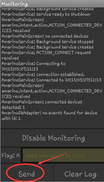
Just input your command and press the Send button here.
Running Result
A few seconds after the upload finishes, open the Amarino app and connect your andorid samart phone with the HC-06 module, simply type “1” or “0” to above column, you will see the on-board LED turn on/off, the output of the Serial Monitor is as below:
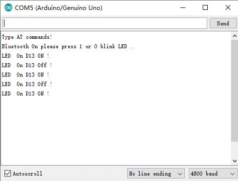
Note: you must choose the correct Baudrate for your serial monitor, be careful!!!


