


Preparations
Hardware
- Osoyoo UNO Board (Fully compatible with Arduino UNO rev.3) x 1
- Barometric Pressure Sensor BMP 180 x 1
- F/M jumpers
- USB Cable x 1
- PC x 1
Software
- Arduino IDE (version 1.6.4+)
In this lesson, we will shoe how to interface an Soil moisture sensor with an Arduino. A soil moisture sensor, also called a hygrometer, measures the amount of moisture, or water, in the soil.
Therefore, we can tell whether the soil has enough moisture or not. So it is a good diagnostic tool for caring for plants of all types.
If the soil is extremely dry, then you will know the plant should be watered.
If the soil is very moist, then you will know that it does not need to be watered.
The soil moisture sensor or the hygrometer is usually used to detect the humidity of the soil. So, it is perfect to build an automatic watering system or to monitor the soil moisture of your plants.
The sensor is set up by two pieces: the electronic board (at the right), and the probe with two pads, that detects the water content (at the left).
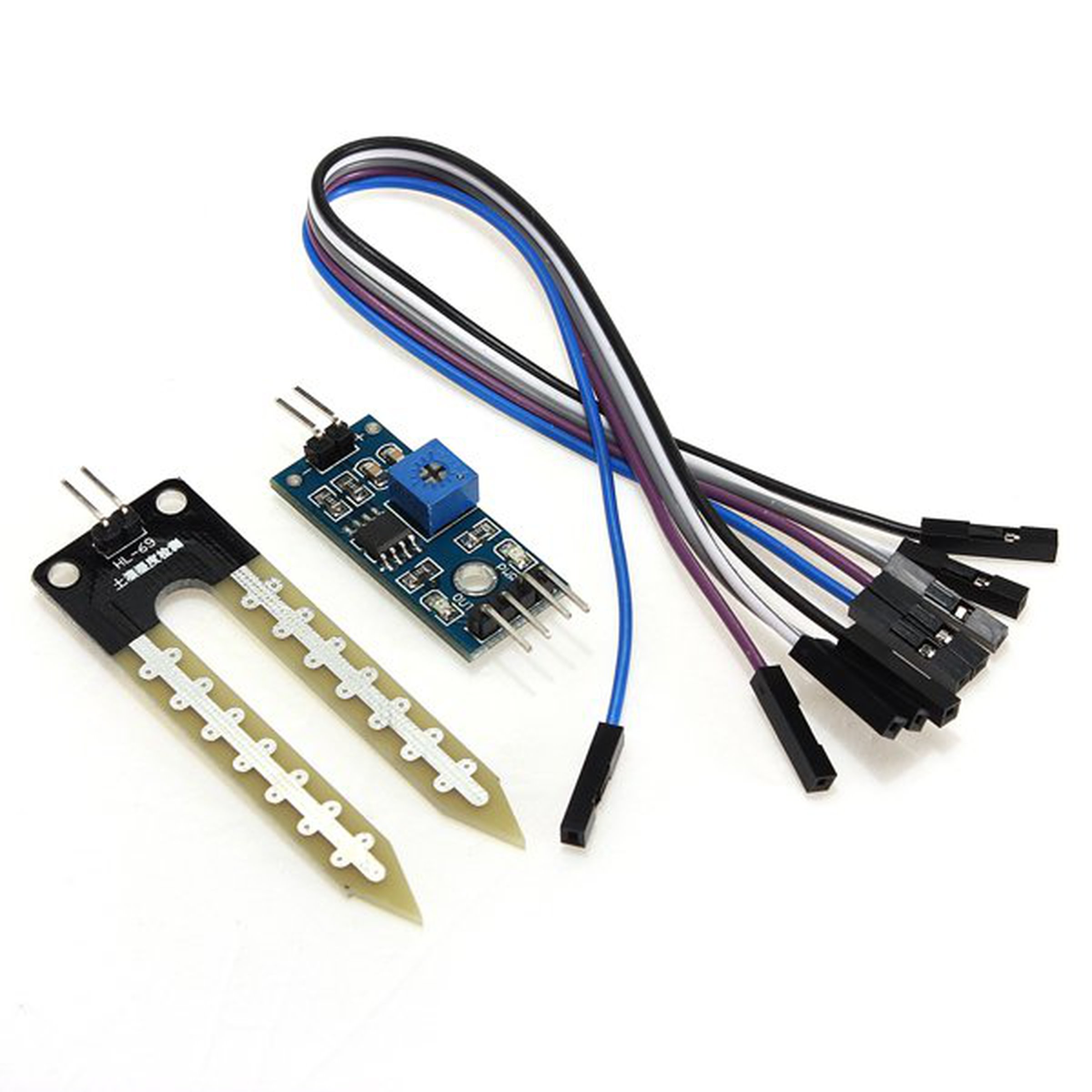
The sensor has a built-in potentiometer for sensitivity adjustment of the digital output (D0), a power LED and a digital output LED, as you can see in the following figure.
This soil moisture sensor has four pins:
The Module also contains a potentiometer which will set the threshold value. This threshold value will be compared by the LM393 comparator. The output LED will light up and down according to this threshold value.
Has both digital and analog functionality, the pin AO will give us an analog signal between the supply value to 0V (For Arduino UNO 5v to 0V) to higher humidity value will be higher, this is due to the operation of the probebecause the higher the humidity is greater conductivity of the soil and therefore increase the value that we measure.
The output of the soil moisture sensor changes in the range of ADC value from 0 to 1023.
This can be represented as moisture value in terms of percentage using formula given below.
Moisture in percentage = 100 – (Analog output * 100)
For zero moisture, we get maximum value of 10-bit ADC, i.e. 1023. This, in turn, gives 0% moisture.
The DO pin will give us a digital signal is “1” when the humidity value is lower than manually establish on the potentiometer and ‘0’ when it is larger. The potentiometer is connected to a comparator LM393 as the probe signal. To use it correctly we must calibrate with different soil samples with different humidities. The green LED will help us in this task because when we have a 1 in DO will turn on.
The soil moisture sensor consists of two probes which are used to measure the Volumetric content of water. The two probes allow the current to pass through the soil and then it gets the resistance value to measure the moisture value.
When there is water, the soil will conduct more electricity which means that there will be less resistance. Therefore, the moisture level will be higher. Dry soil conducts electricity poorly, so when there is less water, then the soil will conduct less electricity which means that there will be more resistance. Therefore, the moisture level will be lower.
This sensor can be connected in two modes; Analog mode and digital mode. First, we will connect it in Analog mode and then we will use it in Digital mode.
This is a simple example for you to understand how you can use the soil moisture sensor in your projects with Arduino.
In this example, you’ll read the analog sensor output values using the Arduino and print those readings in the Arduino IDE serial monitor.
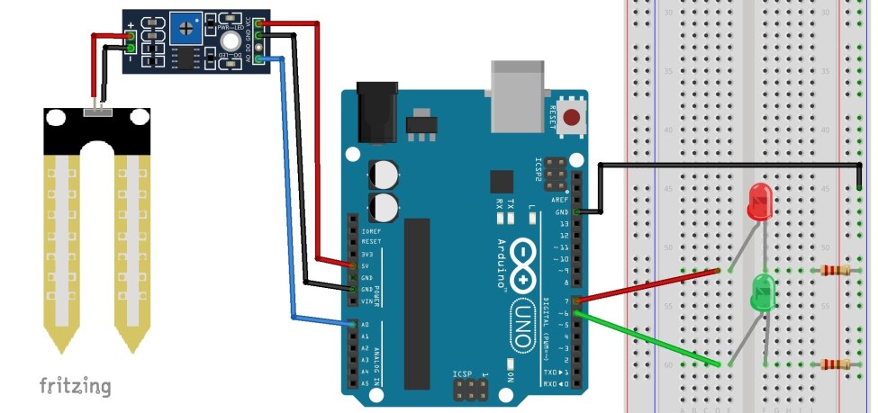
The connections for the soil moisture sensor to the Arduino are as follows:
| Pin | Wiring to Arduino Uno |
| A0 | Analog Pins A0 |
| GND | GND |
| VCC | 3.3V/5V |
To complete the project, follow these schematics:
Upload the following sketch to your Arduino board:
int sensor_pin = A0;
int output_value ;

void setup() {
  Serial.begin(9600);
  Serial.println("Reading From the Sensor ...");
  delay(2000);
  }

void loop() {

  output_value= analogRead(sensor_pin);
  output_value = map(output_value,550,0,0,100);
  Serial.print("Mositure : ");
  Serial.print(output_value);
  Serial.println("%");
  delay(1000);
  }
First of all, we have defined two variables; one for the soil moisture sensor pin and the other for storing the output of the sensor.
int sensor_pin = A0; // Soil Sensor input at Analog PIN A0
int output_value ;
In the setup function, the “Serial.begin(9600)” command will help in communication between the Arduino and serial monitor. Then, we will print the “Reading From the Sensor …” on the serial monitor.
void setup() {
  Serial.begin(9600);
  Serial.println("Reading From the Sensor ...");
  delay(2000);
  }
In the loop function, we will read from the sensor analog pin and will store the values in the “output_ value” variable. Then, we will map the output values to 0-100 because the moisture is measured in percentage. When we took the readings from the dry soil, the sensor value was 550, and in the wet soil, the sensor value was 10. We mapped these values to get the moisture. After that, we printed these values on the serial monitor.
void loop() {
  output_value= analogRead(sensor_pin);
  output_value = map(output_value,550,10,0,100);
  Serial.print("Mositure : ");
  Serial.print(output_value);
  Serial.println("%");
  delay(1000);
  }
Overhere, the connection is same as above example, the below code will show you how to use the sensor to just monitor your plants soil moisture.
int rainPin = A0;
int greenLED = 6;
int redLED = 7;
// you can adjust the threshold value
int thresholdValue = 800;

void setup(){
  pinMode(rainPin, INPUT);
  pinMode(greenLED, OUTPUT);
  pinMode(redLED, OUTPUT);
  digitalWrite(greenLED, LOW);
  digitalWrite(redLED, LOW);
  Serial.begin(9600);
}

void loop() {
  // read the input on analog pin 0:
  int sensorValue = analogRead(rainPin);
  Serial.print(sensorValue);
  if(sensorValue < thresholdValue){
    Serial.println(" - Doesn't need watering");
    digitalWrite(redLED, LOW);
    digitalWrite(greenLED, HIGH);
  }
  else {
    Serial.println(" - Time to water your plant");
    digitalWrite(redLED, HIGH);
    digitalWrite(greenLED, LOW);
  }
  delay(500);
}
Open the Arduino IDE serial monitor to see the values. Then, try your sensor in a wet and in a dry soil and see what happens.
When the analog value goes above a certain threshold, a red LED will turn on (indicates that the plant needs watering), and when the value goes below a certain threshold, a green LED will turn on (indicates that the plant is ok).
To connect the soil moisture sensor in the digital mode, we will connect the digital output of the sensor to the digital pin of the Arduino. The Sensor module contains a potentiometer, which is used to set the threshold value. The threshold value is then compared with the sensor output value using the LM393 comparator which is placed on the sensor module.
The LM393 comparator compares the sensor output value and the threshold value and then gives us the output through the digital pin. When the sensor value is greater than the threshold value, the digital pin will give us 5V and the LED on the sensor will light up. When the sensor value will be less than this threshold value, the digital pin will give us 0V and the light will go down.
The connections for the FC-28 soil moisture sensor and the Arduino in digital mode are as follows.
int led_pin =13;
int sensor_pin =8;
void setup() {
  pinMode(led_pin, OUTPUT);
  pinMode(sensor_pin, INPUT);
}
void loop() {
  if(digitalRead(sensor_pin) == HIGH){
    digitalWrite(led_pin, HIGH);
  } else {
    digitalWrite(led_pin, LOW);
    delay(1000);
  }
}
First of all, we have initialized two variables for connecting the LED pin and the sensor’s digital pin.
int led_pin =13;
int sensor_pin =8;
In the setup function, we have declared the LED pin as the output pin because we will power the LED through that pin. We declared the sensor pin as input pin because the Arduino will take the values from the sensor through that pin.
void setup() {
  pinMode(led_pin, OUTPUT);
  pinMode(sensor_pin, INPUT);
}
In the loop function, we have read from the sensor pin. If the output value of the sensor is higher than the threshold value, then the digital pin will be high and the LED will light up. If the sensor value will be lower than the threshold value, then the LED will go down.
void loop() {
  if(digitalRead(sensor_pin) == HIGH){
    digitalWrite(led_pin, HIGH);
  } else {
    digitalWrite(led_pin, LOW);
    delay(1000);
  }
}
DownLoad Url osoyoo.com