Introduction
In this project, we will go over how to build a smoke sensor circuit with an Arduino board.
The smoke sensor we will use is the MQ-2. This is a sensor that is not only sensitive to smoke, but also to flammable gas.
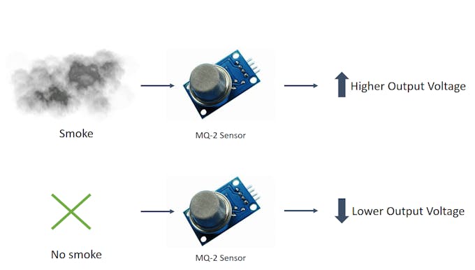
The MQ-2 smoke sensor reports smoke by the voltage level that it outputs. The more smoke there is, the greater the voltage that it outputs. Conversely, the less smoke that it is exposed to, the less voltage it outputs.

Preparations
Hardware
- Osoyoo UNO Board (Fully compatible with Arduino UNO rev.3) x 1
- I2C LCD 1602 Display x 1
- F/M jumpers
- USB Cable x 1
- PC x 1
Software
- Arduino IDE (version 1.6.4+)
About MQ2 Smoke Sensor
The MQ-2 smoke sensor is sensitive to smoke and to the following flammable gases:
- LPG
- Butane
- Propane
- Methane
- Alcohol
- Hydrogen
The resistance of the sensor is different depending on the type of the gas.
The smoke sensor has a built-in potentiometer that allows you to adjust the sensor sensitivity according to how accurate you want to detect gas.
Features
1. Wide detecting scope
2. High sensitivity and fast response
3. Long life and stable
4. Simple drive circuit
Due to its fast response time and high sensitivity, measurements can be taken as soon as possible. The sensor sensitivity can be adjusted by using the potentiometer.
Standard Working Condition
| Symbol |
Parameter Name |
Technical Condition |
Remarks |
| VC |
Circuit voltage |
5V±0.1 |
AC or DC |
| VH |
Heating voltage |
5V±0.1 |
AC or DC |
| RL |
Load resistance |
adjustable |
|
| RH |
Heater resistance |
33Kohm±5% |
Room temperature |
| PH |
Heating consumption |
Less than 800mW |
|
Environment Condition
| Symbol |
Parameter Name |
Technical Condition |
Remarks |
| TO |
Operating Temp. |
-20°C-50°C |
|
| TS |
Storage Temp. |
-20°C-70°C |
|
| RH |
Relative Humidity |
<95% |
|
| O2 |
Oxygen Concentration |
21%(standard condition) Oxygen concentration can affect sensitivity |
Minimum value is 2% |
Sensitivity Characteristics
| Symbol |
Parameter Name |
Technical Condition |
Remarks |
| RS |
Sensor Resistance |
3Kohm-30Kohm (1000ppm iso-butane) |
Detecting concentration scope:
200ppm-5000ppm LPG and propane
300ppm-5000ppm butane
5000ppm-20000ppm methane
300ppm-5000ppm H2
100ppm-2000ppm Alcohol |
| α (3000ppm/1000ppm iso-butane) |
Concentration slope rate |
≤0.6 |
| Standard detecting Condition |
Temp.: 20°C±2°C VC: 5V±0.1
Humidity:65%±5% VH:5V±0.1 |
| Preheating Time |
Over 24 hours |
How does it Work?
The MQ2 has an electrochemical sensor, which changes its resistance for different concentrations of varied gasses. The sensor is connected in series with a variable resistor to form a voltage divider circuit , and the variable resistor is used to change sensitivity. When one of the above gaseous elements comes in contact with the sensor after heating, the sensor’s resistance change. The change in the resistance changes the voltage across the sensor, and this voltage can be read by a microcontroller. The voltage value can be used to find the resistance of the sensor by knowing the reference voltage and the other resistor’s resistance. The sensor has different sensitivity for different types of gasses. The sensitivity characteristic curve is shown below for the different type of gasses.

The voltage that the sensor outputs changes accordingly to the smoke/gas level that exists in the atmosphere. The sensor outputs a voltage that is proportional to the concentration of smoke/gas.

In other words, the relationship between voltage and gas concentration is the following:
- The greaterthe gas concentration,the greaterthe output voltage
- The lowerthe gas concentration,the lowerthe output voltage
Working Mechanism
The output can be an analog signal (A0) that can be read with an analog input of the Arduino or a digital output (D0) that can be read with a digital input of the Arduino.
Note
The sensor value only reflects the approximated trend of gas concentration in a permissible error range, it DOES NOT represent the exact gas concentration. The detection of certain components in the air usually requires a more precise and costly instrument, which cannot be done with a single gas sensor. If your project is aimed at obtaining the gas concentration at a very precise level, then we don’t recommend this gas sensor.
Gas Detection : Basic Example
In this example, the sensor is connected to A0 pin. The voltage read from the sensor is displayed. This value can be used as a threshold to detect any increase/decrease in gas concentration.
void setup() {
    Serial.begin(9600);
}

void loop() {
    float sensor_volt;
    float sensorValue;

    sensorValue = analogRead(A0);
    sensor_volt = sensorValue/1024*5.0;

    Serial.print("sensor_volt = ");
    Serial.print(sensor_volt);
    Serial.println("V");
    delay(1000);
}
Measurement : Approximation
These examples demonstrate ways to know the approximate concentration of Gas. As per the data-sheet of the MQx sensors, these equations are tested for standard conditions and are not calibrated. It may vary based on change in temperature or humidity.
- Keep the Gas Sensor in clean air environment. Upload the program below.
void setup() {
Serial.begin(9600);
}
void loop() {
float sensor_volt;
float RS_air;
float R0;
float sensorValue;
for(int x = 0 ; x < 100 ; x++)
{
sensorValue = sensorValue + analogRead(A0);
}
sensorValue = sensorValue/100.0;
sensor_volt = sensorValue/1024*5.0;
RS_air = (5.0-sensor_volt)/sensor_volt;
R0 = RS_air/9.8;
Serial.print("sensor_volt = ");
Serial.print(sensor_volt);
Serial.println("V");
Serial.print("R0 = ");
Serial.println(R0);
delay(1000);
}
- Then, open the serial monitor of Arduino IDE. Write down the value of R0 and this will be used in the next program. Please write down the R0 after the reading stabilizes.Replace the R0 below with value of R0 tested above . Expose the sensor to any one of the gas listed above.
void setup() {
Serial.begin(9600);
}
void loop() {
float sensor_volt;
float RS_gas;
float ratio;
int sensorValue = analogRead(A0);
sensor_volt=(float)sensorValue/1024*5.0;
RS_gas = (5.0-sensor_volt)/sensor_volt;
ratio = RS_gas/R0;
Serial.print("sensor_volt = ");
Serial.println(sensor_volt);
Serial.print("RS_ratio = ");
Serial.println(RS_gas);
Serial.print("Rs/R0 = ");
Serial.println(ratio);
Serial.print("\n\n");
delay(1000);
}
Arduino MQ-2 Smoke Alarm
The circuit we will build is shown below.
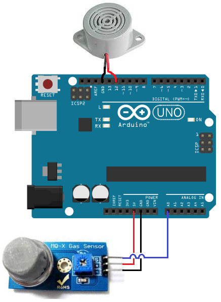
So to power the smoke sensor, we connect pin 2 of the smoke sensor to the 5V terminal of the Arduino and terminal 3 to the GND terminal of the arduino. This gives the smoke sensor the 5 volts it needs to be powered.
The output of the sensor goes into analog pin A0 of the arduino. Through this connection, the Arduino can read the analog voltage output from the sensor. The Arduino board has a built-in analog-to-digital converter, so it is able to read analog values without any external ADC chip.
Depending on the value that the Arduino reads determines the action that will occur with the circuit. We will make it in our code that if the sensor outputs a voltage above a certain threshold, the buzzer will go off, alerting a user that smoke has been detected.
These are all the physical connections in order for our circuit to work.
Code for the Arduino MQ-2 Smoke Sensor Circuit
Being that we’ve just gone over the circuit schematic for the smoke sensor circuit, all we need know is the code necessary to upload to the Arduino for this smoke alarm cicrcuit to work.
The code that we need to upload is shown below.
/*Code for MQ-2 Smoke Sensor Circuit Built with an Arduino Board*/
const int sensorPin= 0;
const int buzzerPin= 13;
int smoke_level;
void setup() {
Serial.begin(115200); //sets the baud rate for data transfer in bits/second
pinMode(sensorPin, INPUT);//the smoke sensor will be an input to the arduino
pinMode(buzzerPin, OUTPUT);//the buzzer serves an output in the circuit
}
void loop() {
smoke_level= analogRead(sensorPin); //arduino reads the value from the smoke sensor
Serial.println(smoke_level);//prints just for debugging purposes, to see what values the sensor is picking up
if(smoke_level > 200){ //if smoke level is greater than 200, the buzzer will go off
digitalWrite(buzzerPin, HIGH);
}
else{
digitalWrite(buzzerPin, LOW);
}
}
The first block of code declares and initializes 3 variables. The sensorPin represents the smoke sensor. It is initialized to 0, because it will be connected to analog pin A0 of the Arduino board. The next variable, buzzerPin, represents the pin that the anode of the buzzer will be connected to; it is initialized to 12 because it will be connected to digital pin D12 of the Arduino board. And the variable, smoke_level, represents the amount of smoke that the smoke sensor picks up.
The next block of code defines the baud rate and the input and output of the circuit. The sensorPin, which is the smoke sensor pin, serves as the input of the circuit. This sensor is input into the Arduino so that the Arduino can read and process the value. The buzzerPin serves as the output. If the smoke level is above a certain threshold, the output of the circuit, the buzzer, will go off.
The next block of code uses the analogRead() function to read the value from the sensorPin (the smoke sensor). This will be a numerical value from 0 to 1023. 0 represents no smoke, while 1023 represents smoke at the absolute maximum highest level. So the variable, smoke_level, represents the smoke level that can range from 0 to 1023. We put a line to print this value just for debugging purposes, so that you can see what values are being returned from this function. In our code, we make it so that if the smoke level rises above 200, we will trigger the buzzer to sound by sending the digital pin D12 high. So 200 is our threshold level. If the smoke level is below this value, then the buzzer does not go off.
This last block of code was the loop() function. This is the part of code that repeats over and over in an infinite loop. This means that our code is always checking to see what the smoke_level is, so that it can know whether to trigger the buzzer or not.
And this is how a smoke sensor works with