Introduction
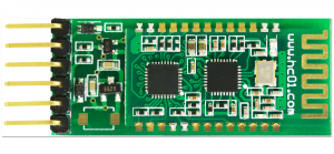
HC-02 Bluetooth serial communication module is based on the Bluetooth V2.0 Bluetooth protocol data transmission module, high stability, ultra low power consumption, industrial grade Bluetooth data transmission module.
Users do not need to care about complex wireless communication configuration and transmission algorithms. They only need to connect to devices through TTL serial port. Powered the HC-02 slave module, and can be connected to the mobile phone for data transmission. In addition, it can be used with HC-05 or HC-06 hosts
(matching code, default is 1234) to connect, can replace a traditional serial line, save wiring work, use
It’s very flexible.
If you need to use iphone or ipad to control your for Arduino project, hc-02 4.0 ble slave module with 6pin baseboard may be a good choice.Fully compatible with ios7.0 or later.Also compatible with Android 4.3 or later.
Please note:
If the version of the Android os is less than 4.3. it is not compatible.
This module supports bluetooth 4.0 ble mode and bluetooth 2.0 mode.
If you are not so familiar with the Bluetooth, you can get more info about blutooth from here.
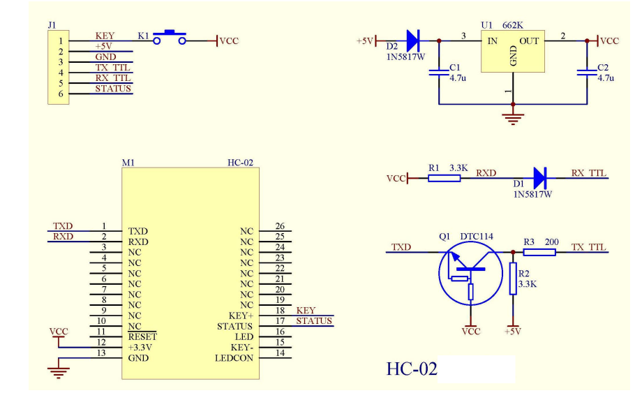
Circuit Diagram of HC-02
Features
| Model |
HC-02 |
Module size |
27*13mm |
| Work band |
2.4G |
Air rate |
2Mbps |
| Communication interface |
UART3.3V TTL |
Antenna interface |
built-in PCB antenna |
| Working voltage |
3.0~3.6V |
Communication current |
30mA |
| Baud rate |
1200~115200bps |
Receiver sensitivity |
-85dBm@2Mbps |
| Communication level |
3.3V |
Working humidity |
10%~90% |
| The transmitting power |
6dBm (maximum) |
Storage temperature |
-40 C ~+85 C |
| Reference distance |
10m |
Working temperatur |
-25 C ~75 C |
- Core module uses HC-08, leads from the module interface includes VCC, GND, TXD, RXD, LED status output pin.
- Led indicate Bluetooth connection status, flashing Bluetooth connectivity, lit the Bluetooth connection and open a port Backplane
- 3.3V LDO input voltage 3.6 6V, the input voltage to prohibit more than 7V
- The interface level 3.3V, can be directly connected the various SCM (51, AVR, PIC, ARM, MSP430, etc.), the 5V MCU also can be connected directly.
- Open to the effective distance of 10 meters, over 10 meters is also possible, but not of this the quality of the connection of the distance do to ensure.
- After the pair when full-duplex serial port to use, do not need to know anything about the Bluetooth protocol, but only supports 8 data bits, 1 stop bit, no parity communication format, which is the most commonly used communication format does not support other formats .
- Compact (3.57cm * 1.52cm), the factory chip production to ensure the placement quality. And sets of transparent heat shrink tubing, dust and beautiful, and anti-static.
Pin Configuration
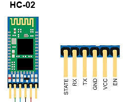
| Pin Number |
Pin Name |
Description |
| 1 |
Enable / Key |
This pin is used to toggle between Data Mode (set low) and AT command mode (set high). By default it is in Data mode |
| 2 |
Vcc |
Powers the module. Connect to +5V/+3.3V Supply voltage |
| 3 |
Ground |
Ground pin of module, connect to system ground. |
| 4 |
TX – Transmitter |
Transmits Serial Data. Everything received via Bluetooth will be given out by this pin as serial data. |
| 5 |
RX – Receiver |
Receive Serial Data. Every serial data given to this pin will be broadcasted via Bluetooth |
| 6 |
State |
The state pin is connected to on board LED, it can be used as a feedback to check if Bluetooth is working properly. |
| 7 |
LED |
Indicates the status of Module
- Blink once in 2 sec: Module has entered Command Mode
- Repeated Blinking: Waiting for connection in Data Mode
- Blink twice in 1 sec: Connection successful in Data Mode
|
Where to use HC-02 Bluetooth module
The HC-02 is a very cool module which can add two-way (full-duplex) wireless functionality to your projects. You can use this module to communicate between two microcontrollers like for Arduino or communicate with any device with Bluetooth functionality like a Phone or Laptop. There are many android applications that are already available which makes this process a lot easier.It’s also fully compatible with the iPhone. The module communicates with the help of USART at 9600 baud rate hence it is easy to interface with any microcontroller that supports USART. We can also configure the default values of the module by using the command mode. So if you looking for a Wireless module that could transfer data from your computer or mobile phone to microcontroller or vice versa then this module might be the right choice for you.
However do not expect this module to transfer multimedia like photos or songs; you might have to look into the CSR8645 module for that.
How to Use the HC-02 Bluetooth module
The HC-02 has two operating modes, one is the Data mode in which it can send and receive data from other Bluetooth devices and the other is the AT Command mode where the default device settings can be changed. We can operate the device in either of these two modes by using the key pin as explained in the pin description.
It is very easy to pair the HC-02 module with microcontrollers because it operates using the Serial Port Protocol (SPP). Simply power the module with +5V/+3.3V and connect the Rx pin of the module to the Tx of MCU and Tx pin of module to Rx of MCU as shown in the figure below
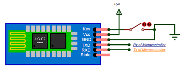
During power up the key pin can be grounded to enter into Command mode, if left free it will by default enter into the data mode. As soon as the module is powered you should be able to discover the Bluetooth device as “HC-02” then connect with it using the default password 1234 and start communicating with it.
Working principle
Connect with MCU

Connect with another Blutooth module

HC-06 is the host, HC-02 is slave, the matching code is consistent (the default is 1234), the baud rate is the same, then power on can be automatically connected. After the first connection, the HC-06 host will automatically match the matching objects. If you want to connect to other modules, you must first remove the pairing memory of the HC-06 host. There is no matching memory from the slave.
Connect with Android phone
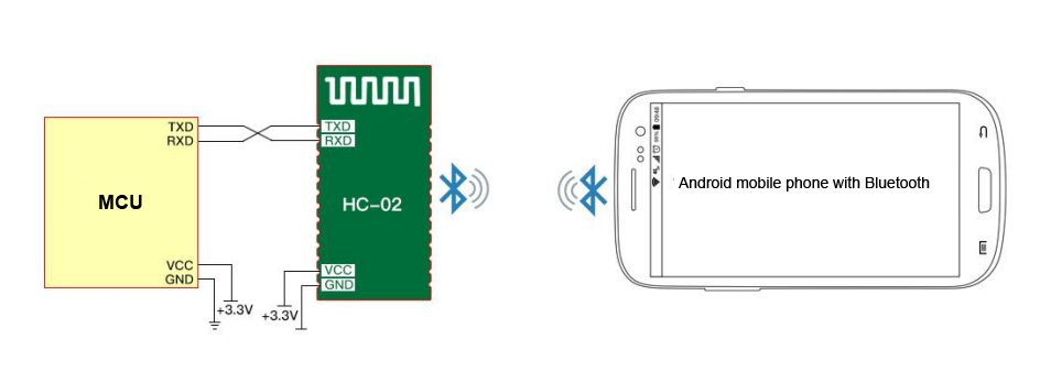
HC-02 can be connected to Android mobile via Bluetooth, and Android can use Android serial assistant software.
Connect with iPhone
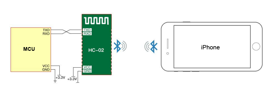
HC-02 can be connected to iPhone 4S and later version iPhone . Communication test needs to download and install BLE serial assistant software.
Note:
Proprietary Service UUID: 49535343-FE7D-4AE5-8FA9-9FAFD205E455
TX UUID: 49535343-1 E4D-4BD9-BA61-23C647249616
RX UUID: 49535343-8841-43F4-A8D4-ECBE34729BB3
Connect with PC

HC-02 can connect to a computer via the HC-06-USB Bluetooth virtual serial port.
HC-02 can connect to the computer’s Bluetooth device to communicate.
Applications
1. Wireless communication between two microcontrollers
2. Communicate with Laptop, Desktops and mobile phones
3. Data Logging application
4. Consumer applications
5. Wireless Robots
6. Home Automation
AT Command
The way to the AT command mode: supply power to the module, it will enter to the AT mode if it
needn’t pair. The interval of command is about 1 second.
Default parameter: Baud rate:9600N81, ID: linvor, Password:1234
1. Test communication
Send: AT (please send it every second)
Back: OK
2. Reset the Bluetooth serial baud rate
Send: AT+BAUD1
Back: OK1200
Send: AT+BAUD2
Back: OK2400
……
1———1200
2———2400
3———4800
4———9600 (Default)
5———19200
6———38400
7———57600
8———115200
9———230400
A———460800
B———921600
C———1382400
PC can’t support the baud rate lager than 115200. The solution is: make the MCU have higher baud
rate (lager than 115200) through programming, and reset the baud rate to low level through the AT
command.
The baud rate reset by the AT command can be kept for the next time even though the power is cut
off.
3. Reset the Bluetooth name
Send: AT+NAMEname
Back: OKname
Example:
Send: AT+NAMEosoyoo
Back: OKname
At this time the Bluetooth name is changed to “osoyoo”.
4. Change the Bluetooth pairing password
Send: AT+PINxxxx
Back: OKsetPIN
More info about the AT Command please check this link.
Sample AT command project
Using Arduino UNO board to send AT command to HC-02 module and change its bluetooth name
Purpose: In many school robotic classrooms, many students are using multiple HC-02 modules with the same bluetooth name “HC-02”, this will cause a lot of conflicts among the students’ projects. So we need to help each student to rename their HC-02 modules to a unique name which won’t conflict with other people.
Here is how to use an Arduino board to send AT command to HC-02 and change its name:
1)Wire Connection
-
HC-02 TX → Arduino D4 (SoftwareSerial RX)
-
HC-02 RX ← Arduino D5 (SoftwareSerial TX)
-
HC-02 VCC → 5V
-
HC-02 GND → GND
-
HC-02 KEY→ HIGH (3.3V or 5V)
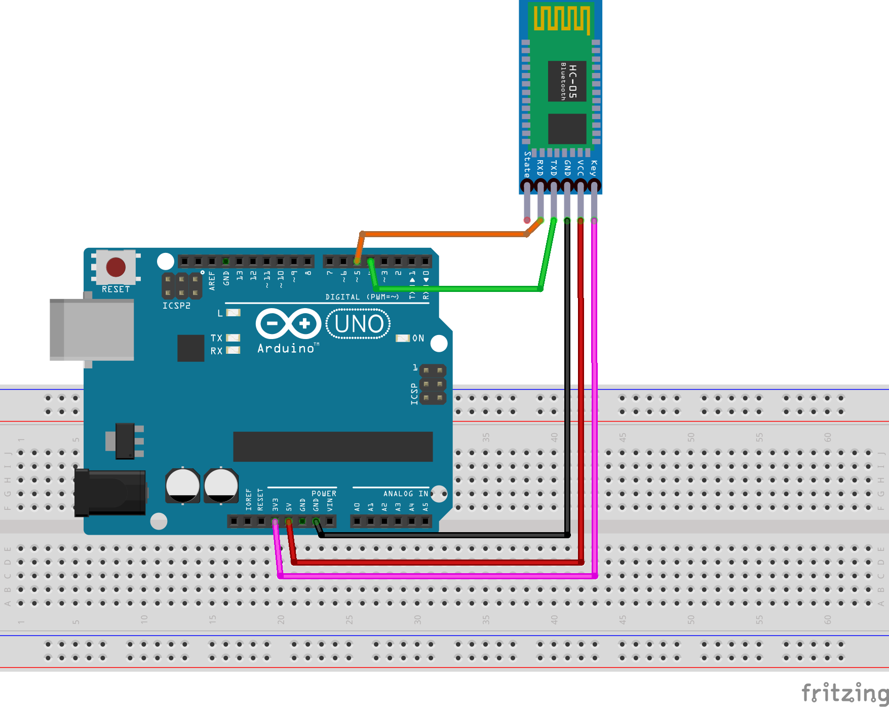
2)Download Arduino AT command sketch from following link:
https://osoyoo.com/driver/2wd/hc02.zip
unzip above file , you will see a folder “hc02”, enter that folder and double click hc02.ino file to open it in Arduino IDE.
3)Test AT command in Serial Monitor
After you upload the hc02.ino code to Arduino, open your Arduino IDE Serial monitor, set baud rate to 9600, set line mode to No Line Ending as following:
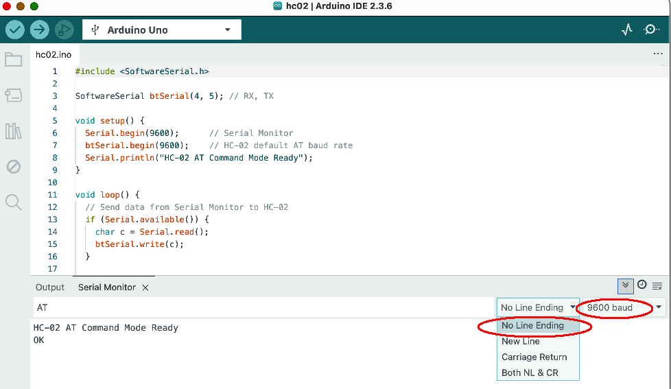
To test the AT command, you can type AT in output field and press enter, now you should see OK in Serial monitor (see above picture). If you can’t see OK, please double check Step 1 to 3.
4)Now you can use AT command to change your HC-02 bluetooth module.
The format is AT+NAMEnewname
For example, if you want to change your HC-02 module name to osoyoo2025, then type following AT command in Serial monitor :
AT+NAMEosoyoo2025
after you press enter button, your Serial monitor will response:
OKsetname
This means your bluetooth module’s new name has been changed to osoyoo2025


this is strange. why does the label say hc-01 and yet your website says hc-02; at-command link does not work
the HC-02 is a sub-category of HC-01 serial bluetooth module. Which HC-02 AT command doesn’t work? Can you give us some more detail so that we can help you? If possible, copy the error message to this comments area.
link gives: The master branch of osoyoo-datasheet does not contain the path bluetooth/HC-05_english_AT_commamd_set.pdf.
I tried plugging in module to arduino got no bluetooth connection
here is the link: https://github.com/osoyoo/osoyoo-datasheet/blob/master/bluetooth/HC-05%20english%20AT%20commamd%20set.pdf
what is pin 34 as mentioned in the first page
Pin 34 is the HC-02 internal pins, you don’t need to care about the detail. You don’t even need to read this AT-Command tutorial because HC-02 has already set default baud rate 9600 by factory . If you don’t want to change baud rate, don’t use any AT command.
You only need to know that HC-02 TX/RX will connect to the RX/TX in Arduino. Then you can set Arduino Serial baud rate 9600 and talk to cell phone APP through HC-02(suppose your cell phone has paired with HC-02) with Arduino Serial.read, Serial.write functions.
is the tx and rx of hc module connected to the tx and rx of arduino
No. You are totally wrong. Serial protocol requires one Device’s TX connects to another device’s RX pin.
Please read our tutorial carefully “….Simply power the module with +5V/+3.3V and connect the Rx pin of the module to the Tx of MCU and Tx pin of module to Rx of MCU….”, also see following circuit graph in the tutorial:

the tx and rx of the mcu represents tx and rx of arduino? or am i wrong? can i get diagram of shield for 2.1 arduino car
if you want to use HC-02 to control V2.1 car, you don’t need to care about how the TX/RX connected. You simply insert the HC-02 into the HC-02 slot in the wifi shield as following:

Make sure the HC-02 TX pin is into the BLE-TX hole and HC-02 RX is in the BLE-RX hole same as above picture.
You also need to use a jumper cap to connect the D4 to B_TX and D5 to B_RX (see the two little red line in above picture). this will make the HC-02 module connect to Arduino software Serial in D4/D5 pin.
then run the code https://osoyoo.com/driver/v2smartcar-lesson7.zip
The code use D4/D5 pin to exchange data with HC-02. HC-02 is a bluetooth bridge between your cell phone APP and Arduino.
For more information about bluetooth APP control V2.1 car through HC-02 module, please read following tutorial:
https://osoyoo.com/2020/05/12/osoyoo-v2-robot-car-lesson-7-imitation-driving-with-bluetooth-app-2/
can i see how the matching connector connects to arduino
We don’t quite understand what is your purpose to ask “how the matching connector connects to arduino?”. I guess your concern might be of following two reasons:
1)You want to use HC-02 to connect Arduino to do some your own Bluetooth communication project? If this is your case, you can connect HC-02 to any digital pin of Arduino by jumper wire. For example, you can connect HC-02 TX pin to Arduino D3 and HC-02 RX pin to Arduino D2, then you need to use Arduino SoftSerial functions to define D3 as SoftRX and D2 as SoftTX by following command:
SoftwareSerial BLTSerial(3, 2);
then you can use BLTSerial.read() or BLTSerial.write() to receiver or send data to remote bluetooth device.
or
2)If you are talking about our V2.1 car lesson 7 bluetooth project. The HC-02 is inserted into Wifi Shield bluetooth slot (see following):

In above project, HC-02 TX is automatically connected D4 and HC-02 RX is automatically connected to D5. So you can read our sample code line 16:
SoftwareSerial BLTSerial(4, 5);
In above code, you can see Arduino D4 is Software RX and must be connected to HC-02 TX pin. The same logic, Arduino D5 is Soft TX and must be connected to Hc-02 RX pin.
lesson 7 code is very good sample software to understand HC-02 bluetooth module communication through Soft Serial port.
If you don’t understand what are Serial Communication and Software Serial communication in Arduino, we suggest you google and read some article to understand the concept first before reading our code, otherwise you might be confused.
I am thinking about using 1). Can you give me example pin to pin diagram and sample code
also what is key and status of hc-02 used for
You don’t need to care about key and status pin. They are used for flashing the firmware of HC-02, you won’t use them in programming. You can leave them empty(not connecting to anything).
Here is a simple example of HC-02 talking to Arduino:
https://osoyoo.com/2018/08/23/hc-02/
Please read above tutorial and sample code carefully. The code receive text message from cell phone APP, APP send bluetooth message to Arduino through HC-02. When the message is “1” , Arduino turn on LED in D13, when message is 0, Arduino turn off D13 LED.
It is quite straight forward.
Hope this helps.