Overhere we will show you what is the flame sensor and how it works, you can follow this lesson to get how to use the flame sensor with the micro bit.
Flame sensor (Infrared receiving triode) is specially used on robots to find the fire source. This sensor is of high sensitivity to flame. Flame sensor is made based on the principle that infrared ray is highly sensitive to flame. It has an infrared receiving tube to detect fire, and then converts the flame brightness into fluctuating level signal. In this lesson, we are going to show how to read the flame sensor’s value, then control the buzzer sound through inputting the fluctuating level signal into micro:bit board.
Parts Needed You will need the following parts:
1x micro:bit
1x Micro B USB Cable
1x micro:bit Breakout (with Headers)
1x Breadboard
5x Jumper Wires
1x Flame Sensor Module
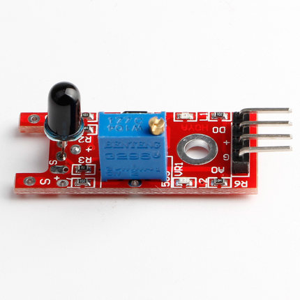
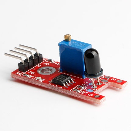
About Flame Sensor
The Flame Sensor can detect flames in the 760 – 1100 nano meter wavelength range. Small flames like a lighter flame can be detected at roughly 0.8m. Detection angle is roughly 60 degrees and the sensor is particularly sensitive to the flame spectrum.The module consists of an IR sensor, potentiometer, OP-Amp circuitry and a led indicator. An on board LM393 op amp is used as a comparator to adjust the sensitivity level. The sensor has a digital and analog output and sensitivity can be adjusted via the blue potentiometer.
FEATURES
The operating voltage is from 3.3 – 5V.
It gives us both analog and digital output.
It has a led indicator, which indicates that whether the flame is detected or not.
The threshold value can be changes by rotating the top of potentiometer.
Flame detection distance, lighter flame test can be triggered within 0.8m, if the intensity of flame is high, the detection distance will be increased.
The detection angle of the flame sensor module is about 60 degrees.
It has both outputs, analog and digital. The analog output gives us a real time voltage output signal on thermal resistance while the digital output allows us to set a threshold via a potentiometer. In our tutorial we are going to use both of these outputs one by one and see how the sensor works.We can use the flame sensor to make an alarm when detecting the fire, for safety purpose in many projects and in many more ways.
WORKING PRINCIPLE
Flame sensor is very sensitive to flame and other lights.
Its analog output provides real time output voltage on the thermal resistance.
When the temperatures reaches at the certain threshold the output high and low signal threshold adjustable via potentio-meter , Its the task of digital output.
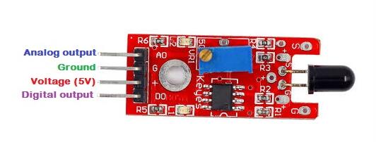
FLAME SENSOR PIN OUT
The pin out of the flame is as follows.
A0: This is the analog pin and this will be connected to the analog pin of the Arduino.
G/GND: This is the ground pin and this will be connected to the ground of the Arduino.
+/VCC: This is the input voltage pin of the sensor and this will be connected to the +5V of Arduino.
D0: This is the digital pin and this will be connected to the digital pin of Arduino.
Example
Overview
In this example, we will show how to build a flame alarm.
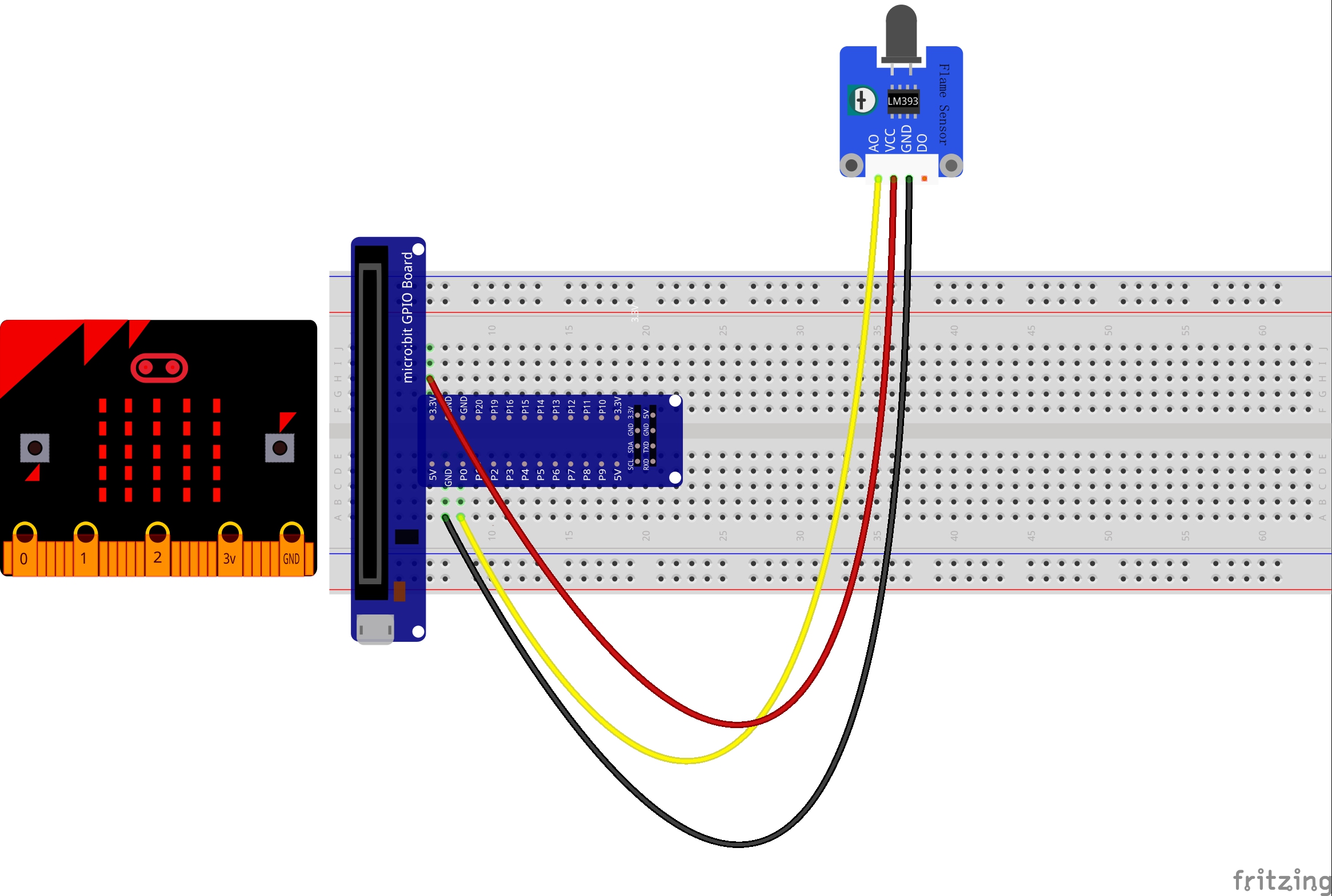
Wiring
Connection for flame sensor:
Flame sensor
Micro bit
VCC
3.3V
GND
GND
A0
P0
Run Your Script
If you are not familiar to make code, don’t worry. At first, you can enter this link: https://makecode.microbit.org/reference to get the reference of microbit block.
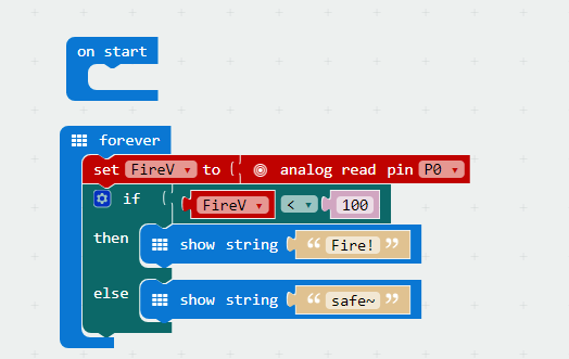
Either copy and paste, or re-create the following code into your own MakeCode editor by clicking the open icon in the upper right-hand corner of the editor window. You can also just download this example by clicking the download button in the lower right-hand corner of the code window.
MICROPYTHON
Testing Result
If flame sensor detects the flame nearby, the led matrix will show “Fire!”, or else it will show “safe~”.