Note: ALL OSOYOO Products for Arduino are Third Party Board which is fully compatitable with Arduino
Content
- Introduction
- Preparations
- About the IR Obstacle Avoidance Sensor
- Example
- Connection
- Upload Sketch
- Program Running Result
Introduction
This is yet another one of those modules with cool possibilities. You could for example, sound an alarm when something got too close or you could change the direction of a robot or vehicle.
The device consists of an Infrared Transmitter, an Infrared Detector, and support circuitry. It only requires three connections. When it detects an obstacle within range it will send an output low.
Preparations
Hardware
- Osoyoo Basic Board (Fully compatible with Arduino UNO rev.3) x 1
- IR Obstacle Avoidance Sensor x 1
- Breadboard x 1
- Jumpers
- USB Cable x 1
- PC x 1
Software
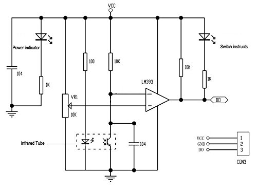
About Obstacle Avoidance Sensor
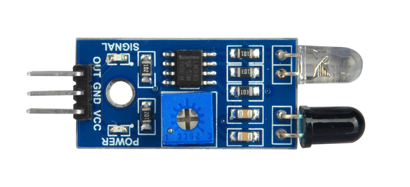
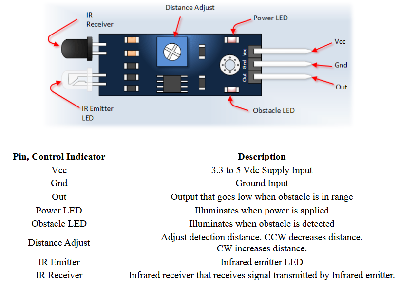
IR Obstacle Detection Module Pin Outs
Specification
- The output port OUT sensor module can be directly connected to the microcontroller IO port , you can directly drive a 5V relay ;
- the module detects the distance 2 ~ 30cm, detection angle 35 °, the distance can detect potential is adjusted
- Can be used for 3-5V DC power supply modules
- When the power is turned on, the red power indicator light
- Using the comparator LM393
- Interface :
1. VCC: External 3.3V-5V voltage (can be directly connected to 5v MCU and 3.3v MCU)
2. GND: GND External
3. OUT: Small board digital output interfaces (0 and 1)
- Connection : VCC-VCC; GND-GND; OUT-IO
- With the screw holes of 3mm , easy fixed installation
- Board Size : 3.1CM * 1.5CM / 1.22 * 0.59″
Working Principle
The IR transmitter sends an infrared signal that, in case of a reflecting surface (e.g. white color), bounces off in some directions including that of the IR receiver that captures the signal detecting the object.
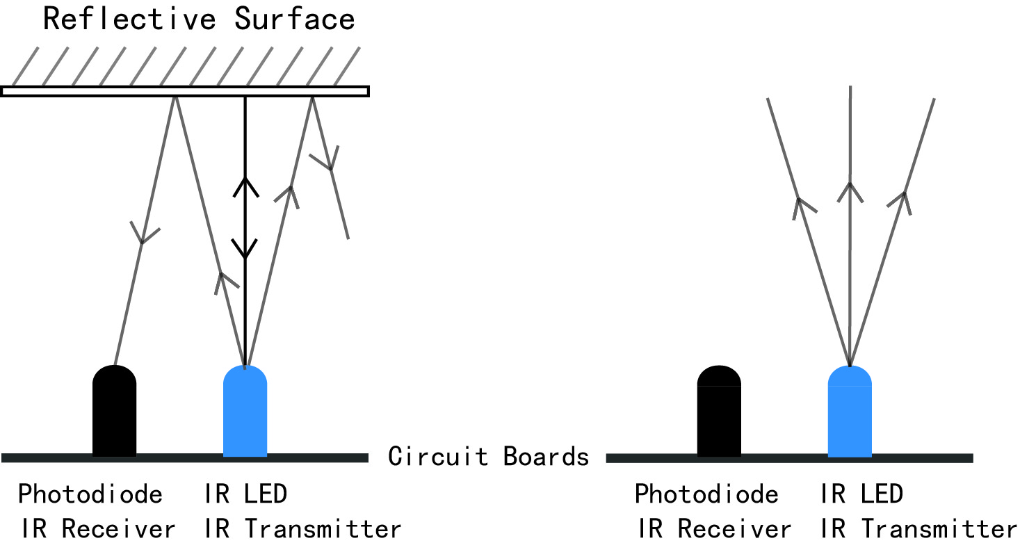
When the surface is absorbent (e.g. black color) the IR signal isn’t reflected and the object cannot be detected by the sensor. This result would occur even if the object is absent.
Examples
Using the Obstacle Avoidance Sensor with board
In this experiment, we will use an Obstacle Avoidance Sensor module and the LED attached to pin 13 of the Osoyoo basic board to build a simple circuit. Since the LED has been attached to pin 13, connect the pin OUT to digital pin 2 of the board. When the Obstacle Avoidance Sensor detects an obstacle, the LED will be on. Otherwise it will be off.
Note: The detection distance of the infrared sensor is adjustable – you may adjust it by the potentiometer.
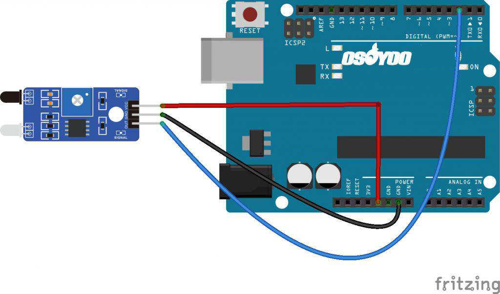
Connection
Make sure the Enable Jumper is placed on the Infrared Obstacle Avoidance sensor, Build the circuit as below digram:
Code Program
After above operations are completed, connect the board to your computer using the USB cable. The green power LED (labelled PWR) should go on.Open the IDE and choose corresponding board type and port type for you project. Then load up the following sketch onto your board.
int LED = 13; // Use the onboard LED
int isObstaclePin = 2;  // This is our input pin
int isObstacle = HIGH;  // HIGH MEANS NO OBSTACLE

void setup() {
  pinMode(LED, OUTPUT);
  pinMode(isObstaclePin, INPUT);
  Serial.begin(9600);
}

void loop() {
  isObstacle = digitalRead(isObstaclePin);
  if (isObstacle == LOW)
  {
    Serial.println("OBSTACLE!!, OBSTACLE!!");
    digitalWrite(LED, HIGH);
  }
  else
  {
    Serial.println("clear");
    digitalWrite(LED, LOW);
  }
  delay(200);
}
Running Result
A few seconds after the upload finishes, place a board in front of the Obstacle Avoidance Sensor, and the LED attached to pin 13 on the Osoyoo Basic board will light up, the on-board obstacle led will turn on. It will turn off when there is no obstacle.
At the same time, choose the corresponding port type for you board and open the Serial Monitor of the IDE, make sure the baudrate is same as your code, move the obstacle in front of the Obstacle Avoidance Sensor, you will see the serial output as below: