Introduction
At sometime or another you may run out of pins on your Arduino board and need to extend it with shift registers. This example is based on the 74HC595. The datasheet refers to the 74HC595 as an “8-bit serial-in, serial or parallel-out shift register with output latches; 3-state.” In other words, you can use it to control 8 outputs at a time while only taking up a few pins on your microcontroller. You can link multiple registers together to extend your output even more.
In this lesson, we will show how to use the 74HC595 to drive a single 7-segment LED display on the Osoyoo Uno board. We’ve already shown how to connect the single 7-segment LED display directly to eight ports on the Uno board. By this way, we can save five ports – considering the Uno board’s limited ports, this is very important.
Preparations
HARDWARE
- Osoyoo UNO Board (Fully compatible with Arduino UNO rev.3) x 1
- One Digit 7-Segment LED Display x 1
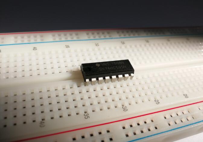
- 74HC595 x 1
- 200 ohm Resistor x 8
- Breadboard x 1
- Jumpers
- USB Cable x 1
- PC x 1
Expanding Reading – About 74HC595
Before I go through the circuit, let’s have a quick look at what the chip is doing, so that we can understand what the code has to do.
The first thing that should be cleared up is what “bits” are, for those of you who aren’t familiar with binary. When we refer to a “bit”, we are referring to one of the numbers that make up the binary value. Unlike normal numbers though, we typically consider the first bit to be the right most one. So, if we take the binary value 10100010, the first bit is actually 0, and the eighth bit is 1. It should also be noted, in case it wasn’t implied, each bit can only be 0 or 1.
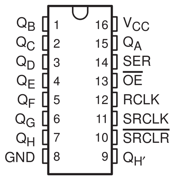
The chip contains eight pins that we can use for output, each of which is associated with a bit in the register. In the case of the 74HC595 IC, we refer to these as QA through to QH. In order to write to these outputs via the Arduino, we have to send a binary value to the shift register, and from that number the shift register can figure out which outputs to use. For example, if we sent the binary value 10100010, the pins highlighted in green in the image below would be active and the ones highlighted in red would be inactive.
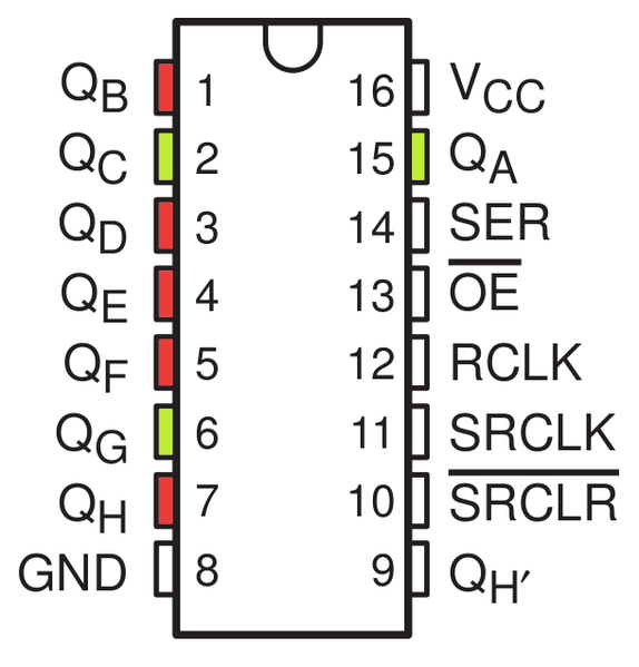
This means that the right most bit that we specify maps to QH, and the left most bit maps to QA. An output is considered active when the bit mapped to it is set to 1. It is important to remember this, as otherwise you will have a very hard time knowing which pins you are using!
The chip also has an OE (output enable) pin, this is used to enable or disable the outputs all at once. You could attach this to a PWM capable Arduino pin and use ‘analogWrite’ to control the brightness of the LEDs. This pin is active low, so we tie it to GND.
Now that we have a basic understanding of how we use bit shifting to specify which pins to use, we can begin hooking it up to our Arduino!
About this project
In the experiment SRCLR (pin10) is connected to 5V (HIGH Level) and OE (pin 13) to GND (LOW Level). Therefore, the data is input into the rising edge of SRCLK and enters the memory register through the rising edge. We use the shiftout() function to output a 8-bit data to the shift register through DS. In the rising edge of the SRCLK, the data in the shift register moves successively one bit in one time, i.e. data in QB moves to QC, and so forth. In the rising edge of RCLK, data in the shift register moves into the memory register. All data will be moved to the memory register after 8 times. Then the data in the memory register is output to the bus (QA-QH). So the 16 characters are displayed in the 7-segment in turn.
Connection
Build the circuit as below:

CODE PROGRAM
After above operations are completed, connect the Arduino board to your computer using the USB cable. The green power LED (labelled PWR) should go on.Open the Graphical Programming software Mixly and follow the next operations:
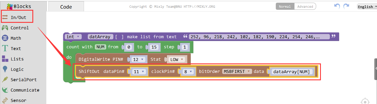
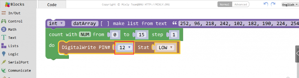
Transform 16 characters in binary, and put them in an array datarray [16].
“0,1,2,3,4,5,6,7,8,9,A,b,C,d,E,F” to “252, 96, 218, 242, 102, 182, 190, 224, 254, 246, 238, 62, 156, 122, 158, 142” 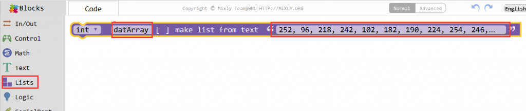 Set the ST-CP(connected to pin 12)to LOW during the data sending.
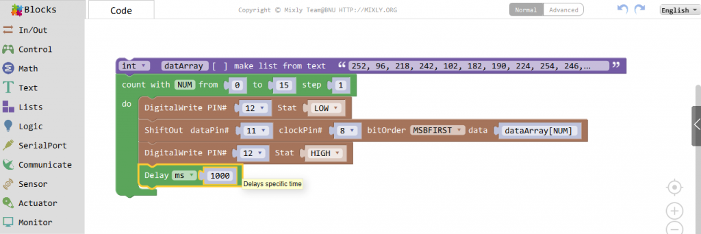
We use the Shiftout function/block to output an 8-bit data to the shift register through DS. The DS is connected to pin 11, and Shcp to pin 8. In the rising edge of the Shcp, the data in the shift registermoves successively one bit in one time, i.e. data in Q1 moves to Q2, and so forth. in the rising edgeof ST-CP data in the shift register moves into the memory register. All data will be moved to thememory register after 8 times. Then the data in the memory register is output to the bus(Q0-Q7)So the 16 characters are displayed in the 7-segment in turn.
 Set ST-CP connected pin 12 to HIGH to save data, and set the delay for 1s.
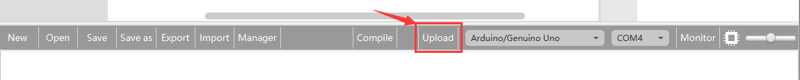
Click Save aftogramming is done. Select the board type and serial port before uploading. For instause a Uno board, just select Arduino/Genuino Uno: if you use a Mega2560, select Arduino/Genuino Mega or Mega2560. 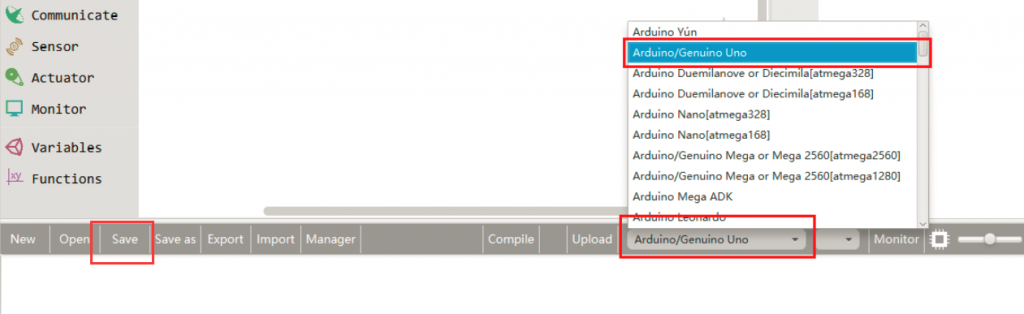
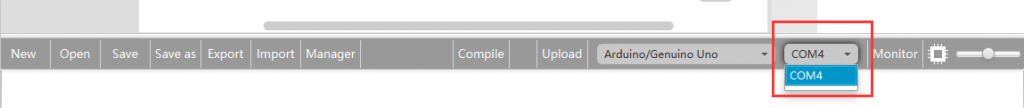
Select the serial device of the Arduino board from the COM menu. This is likely to be COM3 or higher (COM1 and COM2 are usually reserved for hardware serial ports). To find out, you can disconnect your Arduino board and re-open the menu; the entry that disappears should be the Arduino board. Reconnect the board and select that serial port.
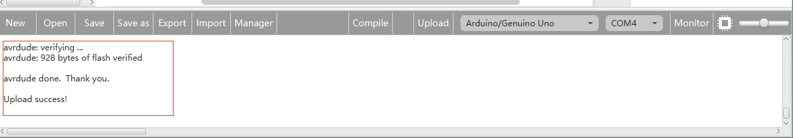
Next,upload the code. If the uploading fails, check and correct the code according to the prompts

Finally, the staus will change to ‘Upload success!’.

Running Result
A few seconds after the upload finishes, you should now see the 7-segment display from 0 to 9 and A to F.