The OSOYOO Magic I/O Shield for Arduino is a powerful board for the beginners. With this Magic board, we can easily connect various sensors and actuators much easier than before.
In this lesson, we will show how to use the OSOYOO light detect module to work with the OSOYOO UNO board, we will monitor the output of this sensor, allow the OSOYOO Basic Board for Arduino to know how light or dark it is. When the light falls below a certain level, the OSOYOO Basic Board for Arduino turns on an LED.
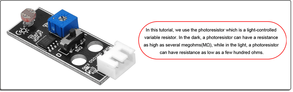
The OSOYOO Light Detect module incorporates a photocell, is a commonly used sensor in a wide variety of applications from DIY projects to industrial automation. Typically, the resistance of the LDR or Photoresistor will decrease when the ambient light intensity increases. This means that the output signal from this module will be HIGH in bright light, and LOW in the dark.
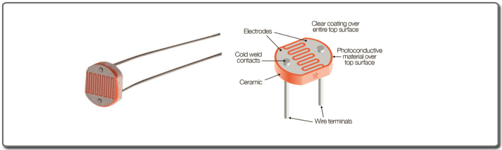
Photocells are sensors that allow you to detect light. They are small, inexpensive, low-power, easy to use and don’t wear out. For that reason they often appear in toys, gadgets and appliances. They are often referred to as CdS cells (they are made of Cadmium-Sulfide), light-dependent resistors (LDR), and photoresistors.
Photocells are basically a resistor that changes its resistive value (in ohms Ω) depending on how much light is shining onto the squiggly face.When it is dark, the resistance of a photoresistor may be as high as a few MΩ. When it is light, however, the resistance of a photoresistor may be as low as a few hundred ohms. They are very low cost, easy to get in many sizes and specifications, but are very innacurate. Each photocell sensor will act a little differently than the other, even if they are from the same batch. The variations can be really large, 50% or higher! For this reason, they shouldn’t be used to try to determine precise light levels in lux or millicandela. Instead, you can expect to only be able to determine basic light changes.
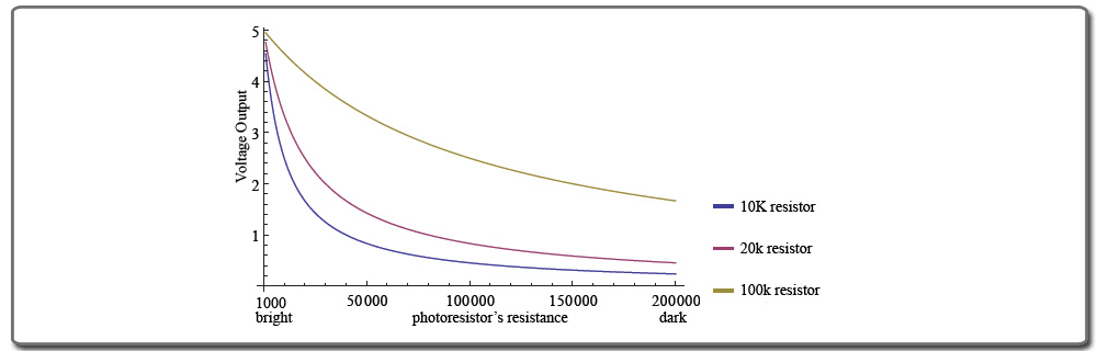
This graph indicates approximately the resistance of the sensor at different light levels:
Light sensor is commonly seen in our daily life and is mainly used in intelligent switch, also in common electronic design.
To make it more easier and effective, we supply corresponding modules. Light sensor is a semiconductor. It has features of high sensitivity, quick response, spectral characteristic, and R-value consistence, maintaining high stability and reliability in environment extremes such as high temperature, high humidity.
It’s widely used in automatic control switch fields like cameras, garden solar lights, lawn lamps, money detectors, quartz clocks, music cups, gift boxes, mini night lights, sound and light control switches, etc.
OSOYOO Basic Board for Arduino (Fully compatible with Arduino UNO rev.3) x 1
OSOYOO Magic I/O Shield for Arduino x1
Light Detect Module x 1
LED Module x 1
OSOYOO 3-Pin PNP cable x 2
USB Cable x 1
PC x 1
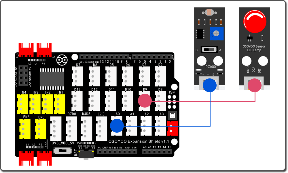
First, please plug Osoyoo Magic I/O shield into UNO board:
Then connect the modules to the ports of the Magic I/O shield with two 3-pin PNP cables as below:
LED Module – D9
Light Detect Module – A0
Notice: Shut off your battery or Unplug your power adapter when upload sketch code to OSOYOO Basic Board for Arduino.
After above operations are completed, connect the OSOYOO Basic Board for Arduino to your computer using the USB cable. The green power LED (labelled PWR) should go on.
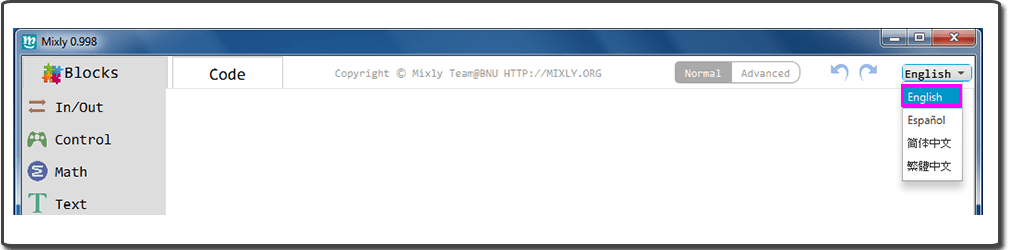
Open the Graphical Programming softwareMixly, if Mixly is not English, you should change the language first:
You can download the code directly, then click “Open” in Mixly to choose the code you download:
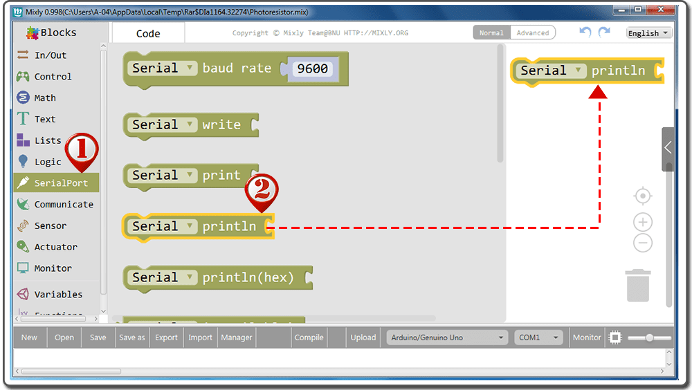
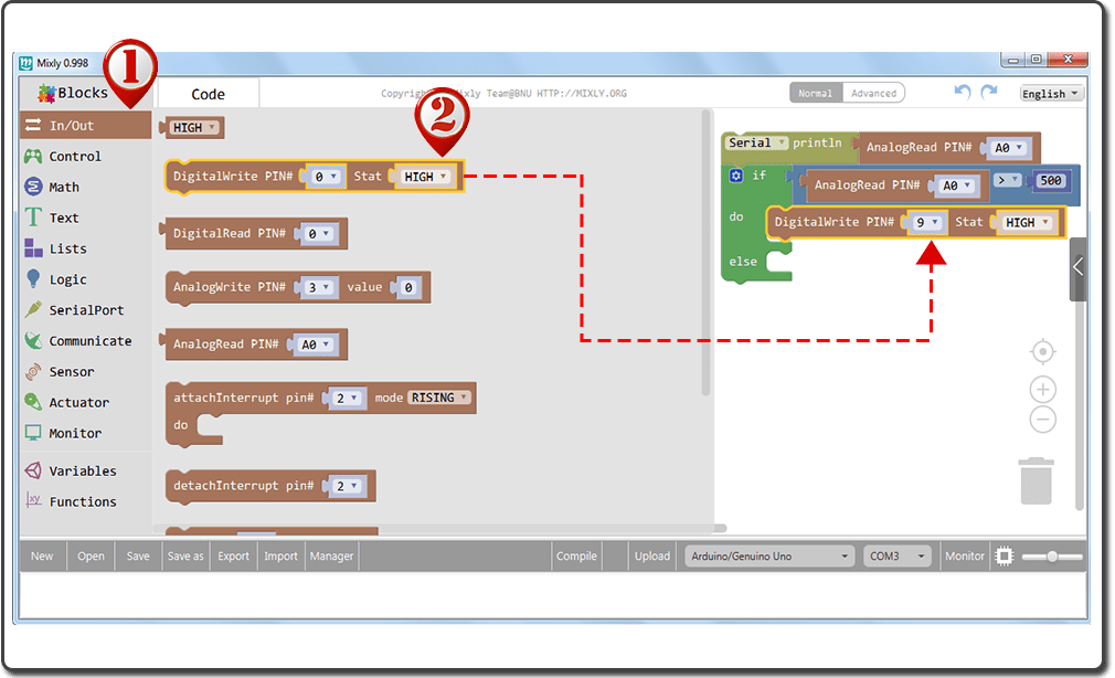
Drag “AnalogWrite PIN#” to fit with “Serial printIn” block;
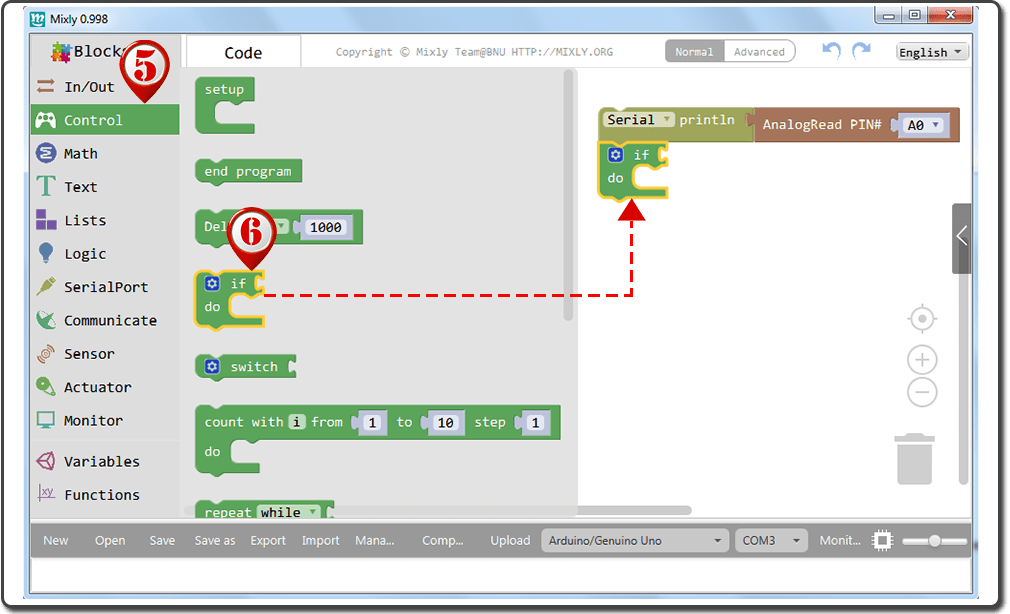
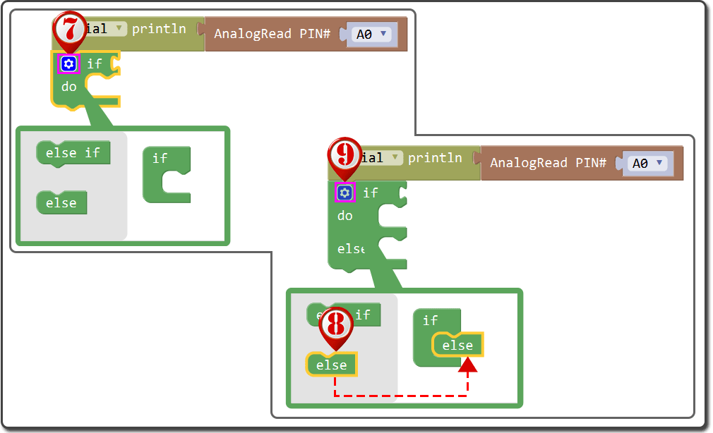
Click “Control” block;
Drag “if do” block under “Serial printIn” block, fit the two blocks;
Click the setting icon in “if do” block, then you’ll see branch blocks;
Drag “else” block to fit “if” block;
Click the setting icon in “if do else” block to close the branch blocks.
Then follow the below operations:
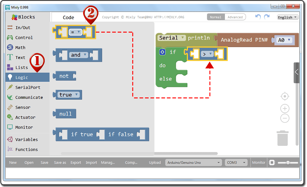
Click “Logic” block;
Drag the first block “=” to fit “if do else” block, and change”=” to “>“;
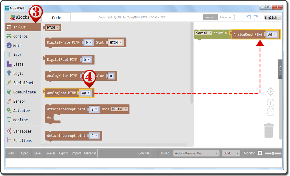
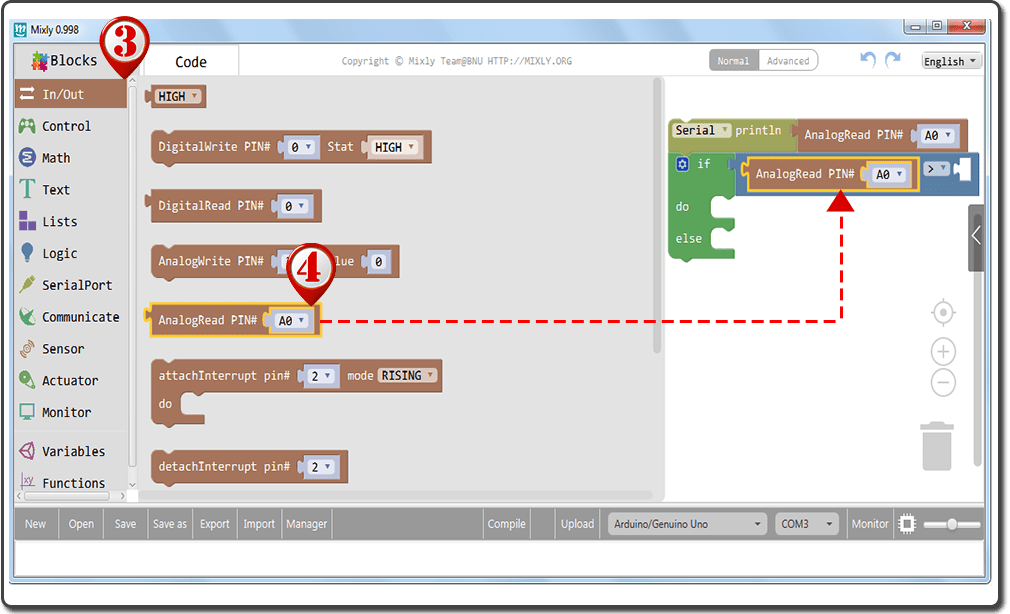
Click “In/Out” block;
Drag “AnalogWrite PIN#” to fit the left slot of “=” block;
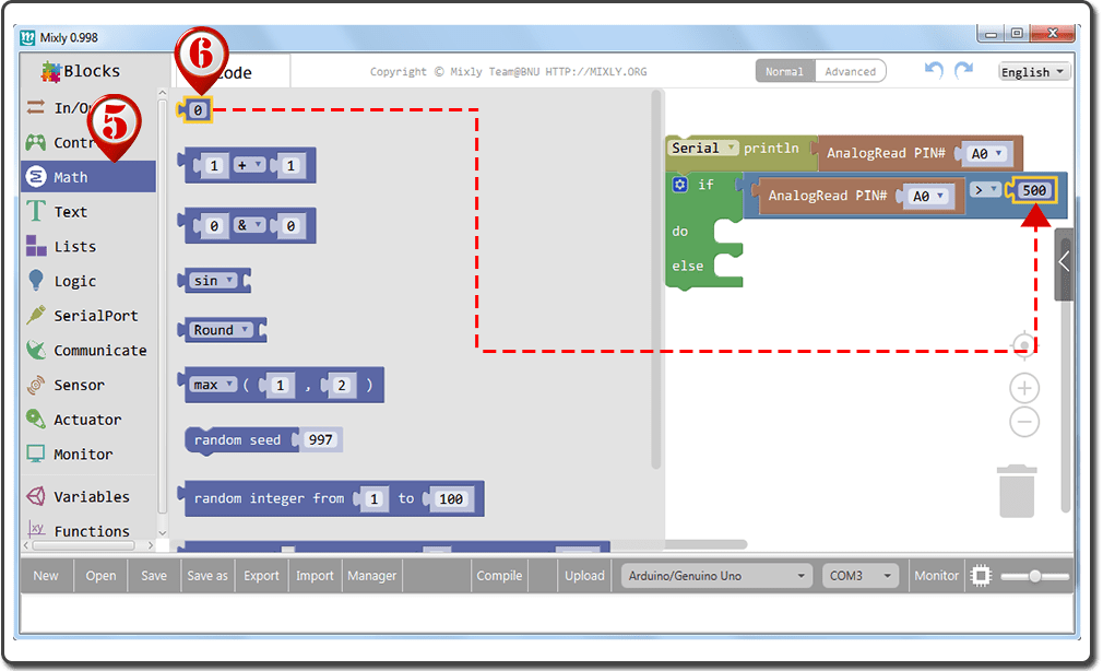
Click “Math” block;
Drag the first block “0” to fit the right slot of “=” block, and change “0” to “500” .
Click “In/Out” block;
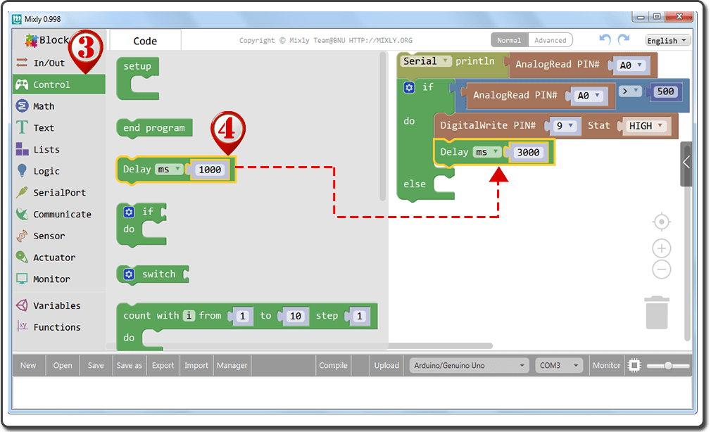
Drag “DigitalWrite PIN#” to fit “if do else” block, and edit the parameter to “DigitalWrite PIN# 9 Stat HIGH“;
Click “Control” block;
Drag “Delay” block under “DigitalWrite PIN#” block, fit the two blocks, and edit the parameter to “Delay ms 3000“;
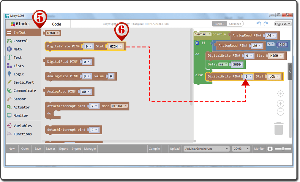
Click “In/Out” block;
Drag “DigitalWrite PIN#” to fit “if do else” block, and edit the parameter to “DigitalWrite PIN# 9 Stat LOW“.
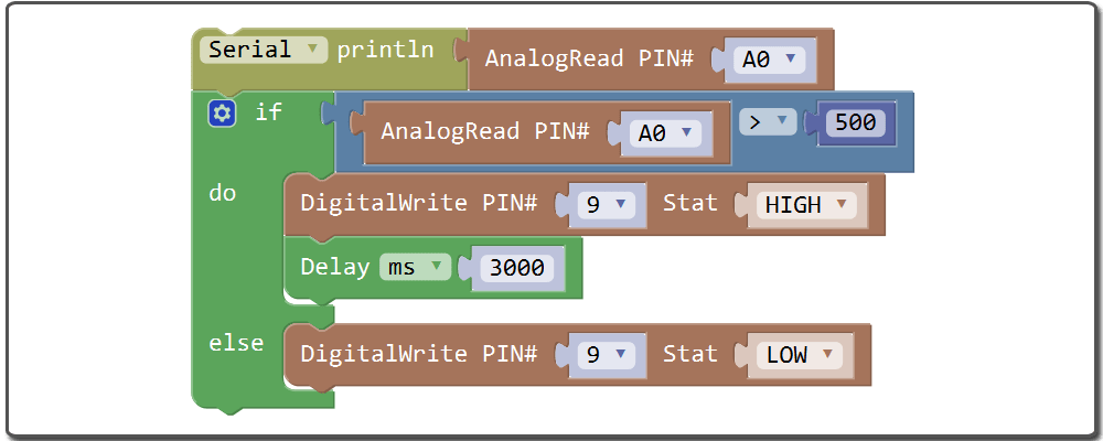
In this experiment, we will connect a photoresistor to an OSOYOO Basic Board for Arduino analog input and read the value with the analogRead() function. Depending on the value the OSOYOO Basic Board for Arduino reads, the program will then set pin 9 HIGH or LOW to turn on or turn off the LED night lights. The threshold value is 500. When the analog value read is less than 500, the OSOYOO Basic Board for Arduino will turn the LEDs on. When the analog value it reads is more than 500, the OSOYOO Basic Board for Arduino will turn the LEDs off.
The whole program blocks are as following:
After above operations are completed, do as follows:
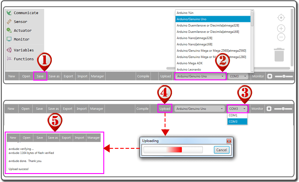
Click Save after programming is done.
Select the board type and serial port before uploading. For instause an UNO board, just select Arduino/Genuino Uno: if you use a Mega2560, select Arduino/Genuino Mega or Mega2560.
Select the serial device of the OSOYOO Basic Board for Arduino from the COM menu. This is likely to be COM3 or higher (COM1 and COM2 are usually reserved for hardware serial ports). To find out, you can disconnect your OSOYOO Basic Board for Arduino and re-open the menu; the entry that disappears should be the OSOYOO Basic Board for Arduino. Reconnect the board and select that serial port.
Next,upload the code. If the uploading fails, check and correct the code according to the prompts.
Finally, the status will change to ‘Upload success!’.
If the room is lighted, the LEDs should not light. Try getting them to turn on it by covering the photoresistor. Remove the cover and observe that they turn off again.
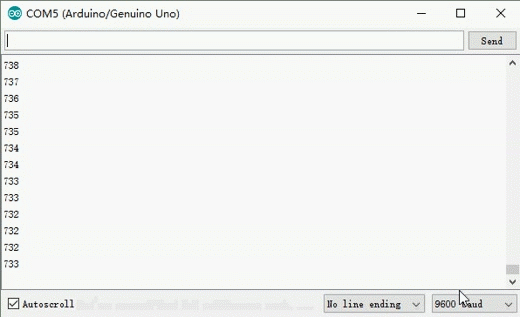
In the same time, open the Serial Monitor and you will get the output data as below :
Note:
When you are using the Serial Monitor, please make sure the baudrate setting is same as your sketch definition.