In Lesson 1, we learned how to use the OSOYOO Basic Main board to make a simple web server and display “Hello World” in your remote browser. This uses a protocol called HTTP to exchange data with the remote client device (browser).
In this lesson, we will teach you to use a very simple and powerful protocol called UDP, which is commonly used for email service and control signal. We will use a cell phone app to turn on/off an LED in the IDE remotely through the UDP protocol.
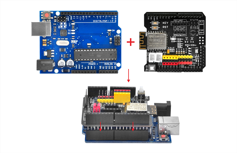
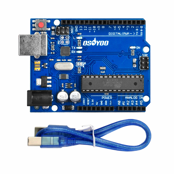
OSOYOO Basic board x 1
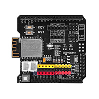
OSOYOO ESP8266 Wi-Fi Shield x 1
USB cable x 1
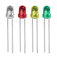
LED x 1
200 ohm resistor x 1
First, please insert the ESP8266 Wi-Fi Shield into your Basic Board
Make sure the jumper cap is connected from E_TX to D4 and E_RX to D5.
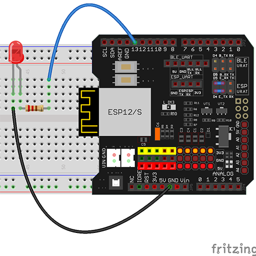
Then connect the long pin of the LED to D13 in the Wi-Fi shield through a 200 ohm resistor, and the short pin to GND. The circuit is shown below
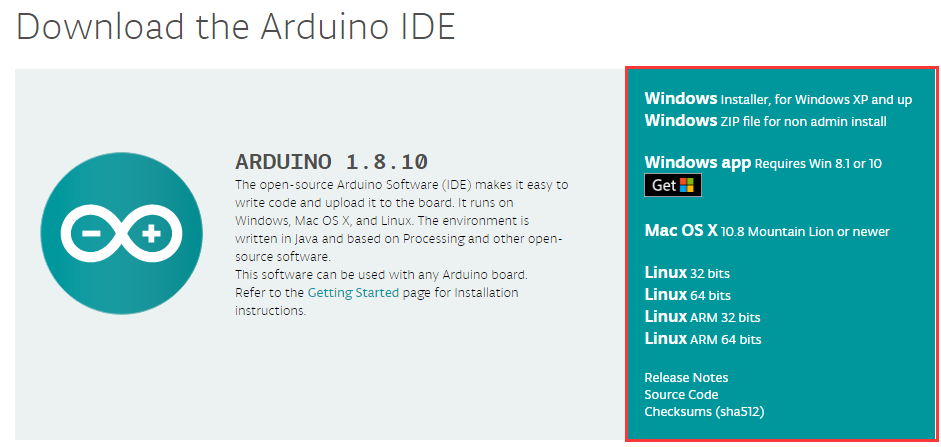
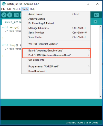
Step A: Install the latest IDE (If you have IDE version after 1.1.16, please skip this step).
Unzip the downloaded file and enter the folder “esp8266-lesson2”.
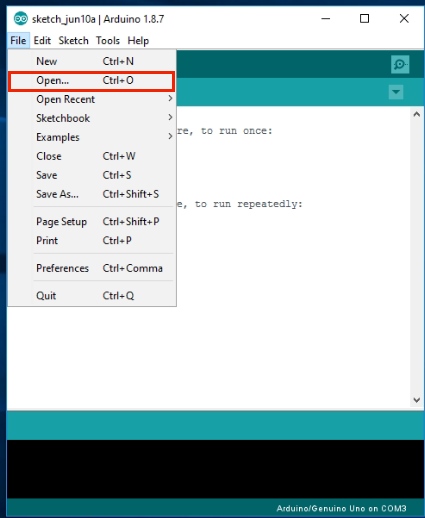
Step E: In the IDE, click “File” ⇾ click “Open” ⇾ choose code “esp8266-lesson2” and load up the sketch onto your IDE.
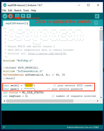
In the sketch, find the following lines:
char ssid[] = "******"; // your network SSID (name)
char pass[] = "******"; // your network password
Please replace the "******" with your correct Wi-Fi SSID and password, otherwise your project
cannot connect to the internet.
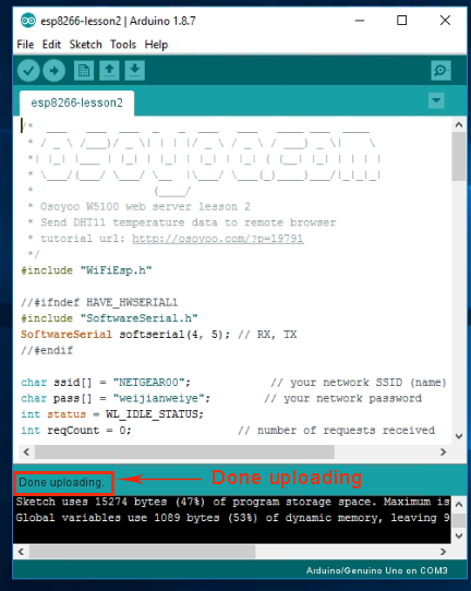
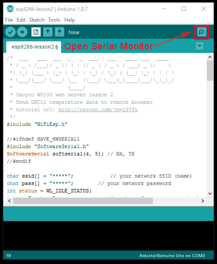
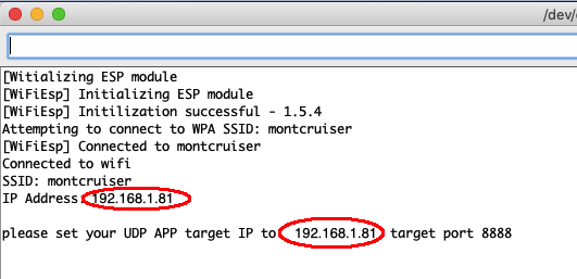
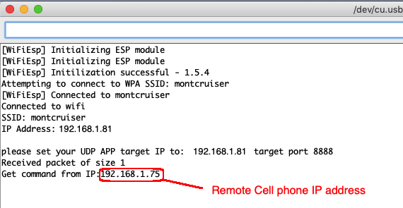
Step F: Now upload the sketch to the board and open your Serial Monitor. You can see that your router will assign an IP address to your IDE as following:
In the above example, “192.168.1.81” is the IP address of my ESP8266 Wi-Fi Shield, and we need to set this IP address in our app in the next step.
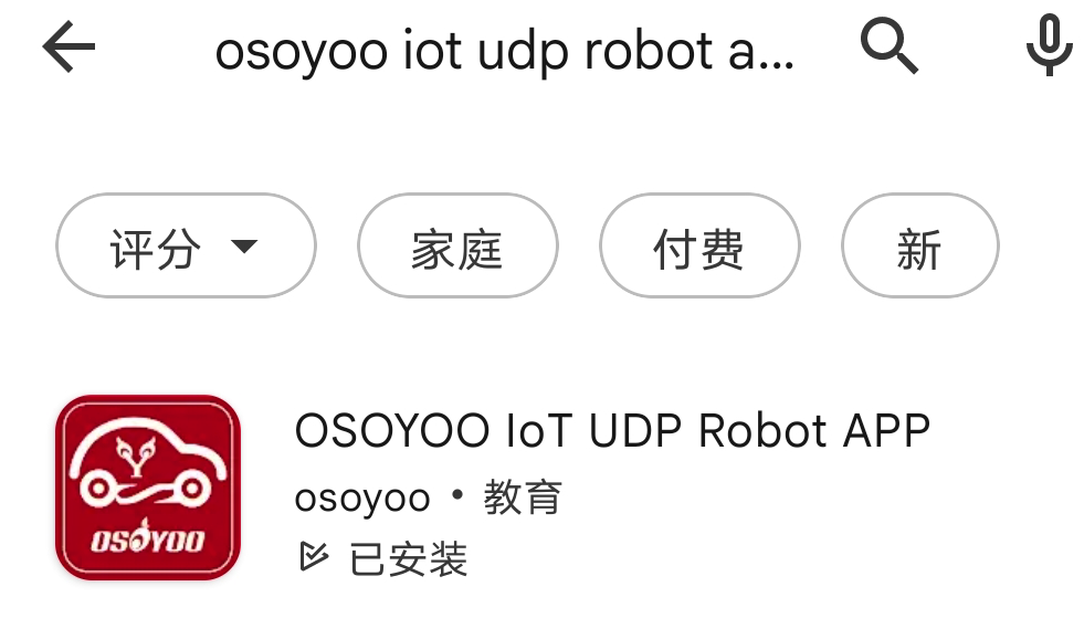
Step G: Install the UDP send mobile app. You can use any UDP send app to run this lesson. In this lesson, we use the “OSOYOO IOT UDP Robot” app to make the test. In Google Play or Apple Store, please search for the keywords “OSOYOO IOT UDP Robot app”, and you will find a red icon app.(If you can not find this APP in Google Play,
you can directly download the APP from following link: https://osoyoo.com/driver/udp-app.apk)
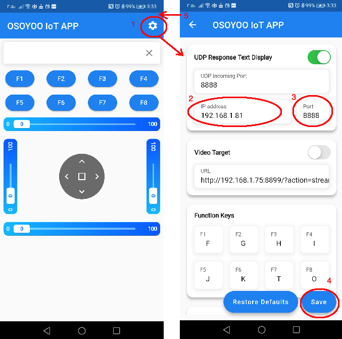
Make sure your cell phone is on the same local network as the Arduino. Open the app, click “Settings”, enter your Arduino IP address from Step F and port to “8888” in the settings
In the app UI screen, click “F1” button, your LED will turn on. Then click “F2” button, your LED will turn off.
After you click the cell phone button, the Arduino Serial monitor will also show your cell phone’s IP address as follows:
Please write down this IP address, as we will use it in the next lesson.
FAQs about the Wi-Fi UDP app and sketch code:
Q1) What happens when you press buttons in the OSOYOO Wi-Fi UDP Robot Car app?
A: When you press a button in the app, the app will send a single-letter message through the UDP protocol to the target device (in this example, our Wi-Fi Shield).
Button
UDP message
F1
F
F2
G
F3
H
F4
I
F5
J
F6
K
▲
A
▼
B
►
R
◄
L
⮸
E
Q2: How do you react to the app command?
A: In Our sample code (esp8266-lesson2.ino) lines 69 to 76, the switch statement handles the remote UDP command.
      switch (c)    //serial control instructions
      {

        case 'F': digitalWrite(ledPin, HIGH) ;break; //TURN ON LED
        case 'G':digitalWrite(ledPin, LOW) ;break; //TURN OFF LED

        default:break;
      }
In the above code lines, variable “c” is the message we got from the mobile app. If the message is “F”, it means the F1 key is pressed, and we should turn on the LED. If the message is “G”, it means F2 is pressed, and we need to turn off the LED.
When using this tutorial, averything works as expected EXCEPT:
My serial monitor doesnot show the IP address of my mobile phone.
I am directed to write this down because it will be required in the next tutorial.
I am using:
Arduino IDE 2.0.4
OSOYOO WiFi Internet of things learning kit for arduino
Arduino sketch downloaded today (3/17/23) from OSOYOO website “esp8266-lesson2.zip
Serial monitor displays:
please set your UDP APP target IP to: xx.x.x.xx target port 8888
Received packet of size 1
Received packet of size 1
Received packet of size 1
What causes the APP to stop working and require it restarted to get it to work after say 45 seconds of no use? Is this a known issue with Apple phones or?


 Make sure the jumper cap is connected from E_TX to D4 and E_RX to D5.
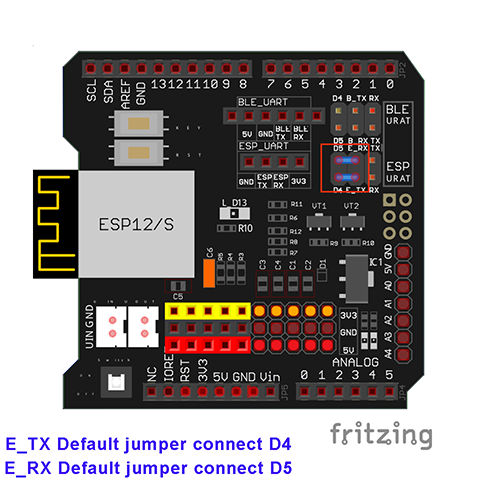


When using this tutorial, averything works as expected EXCEPT:
My serial monitor doesnot show the IP address of my mobile phone.
I am directed to write this down because it will be required in the next tutorial.
I am using:
Arduino IDE 2.0.4
OSOYOO WiFi Internet of things learning kit for arduino
Arduino sketch downloaded today (3/17/23) from OSOYOO website “esp8266-lesson2.zip
Serial monitor displays:
please set your UDP APP target IP to: xx.x.x.xx target port 8888
Received packet of size 1
Received packet of size 1
Received packet of size 1
In Step F, the Serial monitor will show your Arduino IP address. Did you get your Arduino IP address and set it to your cell phone?
What causes the APP to stop working and require it restarted to get it to work after say 45 seconds of no use? Is this a known issue with Apple phones or?
we never heard of this issue before. Are you using a new version of iPhone or Android phone?