| Buy from US |
Buy from UK |
Buy from DE |
Buy from IT |
Buy from FR |
Buy from ES |
ここでご購入を! |
 |
 |
 |
 |
 |
 |
 |

In Lesson 2, we learned how to use a browser to send control signals to a remote device and turn On/Off an LED. In this lesson, we’ll show you how to read remote sensor data on your cell phone APP. We will use a photoresistor (light sensor) to read the remote environment light value. This is very useful in farms and greenhouses to control the light of plants.

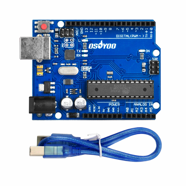
OSOYOO Basic board x 1
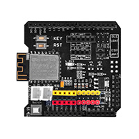
OSOYOO ESP8266 Wi-Fi Shield x 1
Photoresistor sensor Module x 1
USB cable x 1
Jumper wires several

First, please insert the ESP8266 Wi-Fi Shield into your basic board.

Make sure the jumper cap is connected to E_TX on D4 and E_RX on D5.
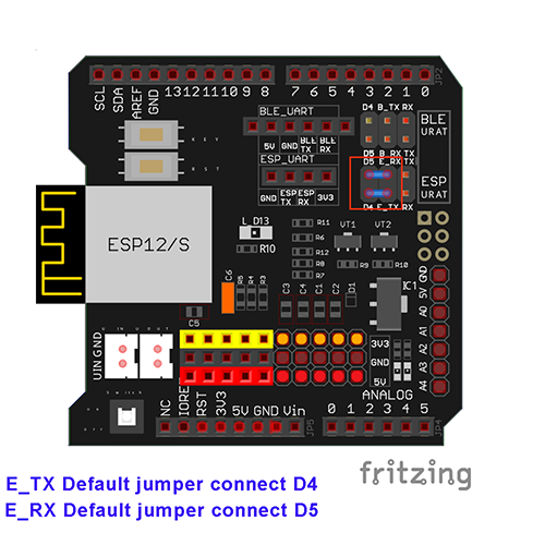
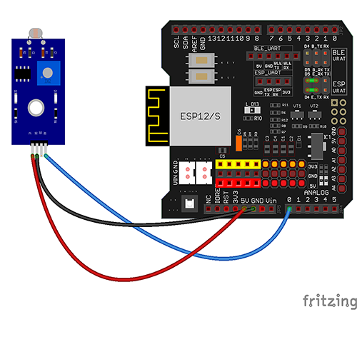
Connect your photoresistor with the main board as shown in the following diagram.
A couple of notes before you get started:
-
-
-
- The photoresistor uses analog output, so you will need to use the analog pins on the main board.
- In this example, we are using a 5V power supply from the main board, but we could use the 3.3V as well.
- The provided diagram is just an example of how to connect the hardware. There are many ways to connect devices, so try what works best for you!
| OSOYOO Basic Board |
Photoresistor sensor module |
| A0 |
S |
| GND |
– |
| 5V |
+ |

Step A) Install the latest IDE from https://www.arduino.cc/en/Main/Software?setlang=en. If you have an IDE version after 1.1.16, please skip this step.
Step B) Connect the OSOYOO Basic board to the computer via a USB cable.
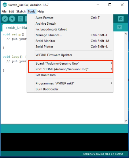
Step C) Open the IDE and choose the corresponding board type and port type for your project.
-
-
- Board:”Arduino/Genuino UNO”
- Port: Choose your own Serial Port for your mainboard
Step D) Download the sketch file from: https://osoyoo.com/driver/wifi-iot/lesson3/wifi-lesson3.zip
Unzip the downloaded file and enter the folder wifi-lesson3.
Step E) IDE: Click “File” -> click “Open” -> choose code “wifi-lesson3”, load up the sketch onto your IDE.

In the sketch, find the following lines:
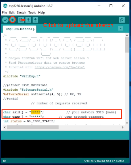
char ssid[] = "******"; // replace *** with your wifi network SSID (name)
char pass[] = "******"; // replace *** with your wifi network password
Please replace the ****** with your correct wifi SSID and password, otherwise your
project will not be able to connect to the internet.

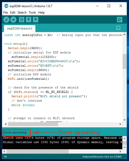
Step F) Upload the sketch to your IDE.

Step A) Open your Serial Monitor. You will see that your router has assigned an IP address to your IDE, as shown in the following example:
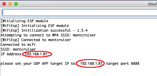
In the above example, 192.168.1.81 is the IP address of my IDE. We need to set this IP address in our APP in the next step.
Step B) Open your OSOYOO IOT UDP Robot APP. If you haven’t installed this APP, please read the APP installation section in Lesson 2.
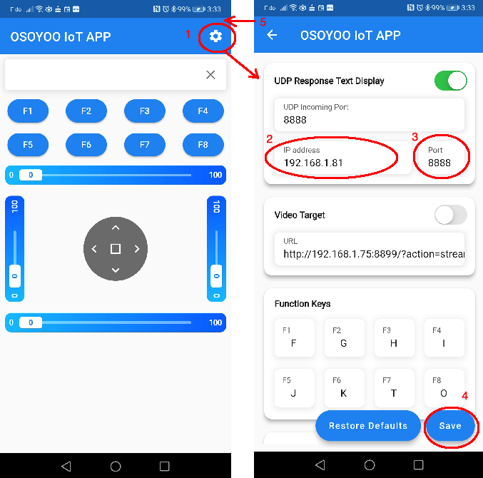
Step C) Make sure your cell phone is on the same local network as the Arduino. Open the APP, click on “Settings”, enter your Arduino IP address from Step A and port number 8888 in the settings.
Now press any key on your APP, and your screen will display something like the following picture:
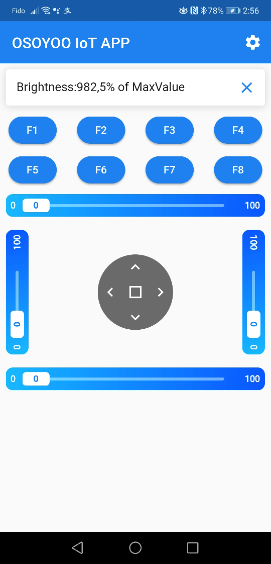
The value of 982, 5% of the maximum sensor value, means the environment is very dark.
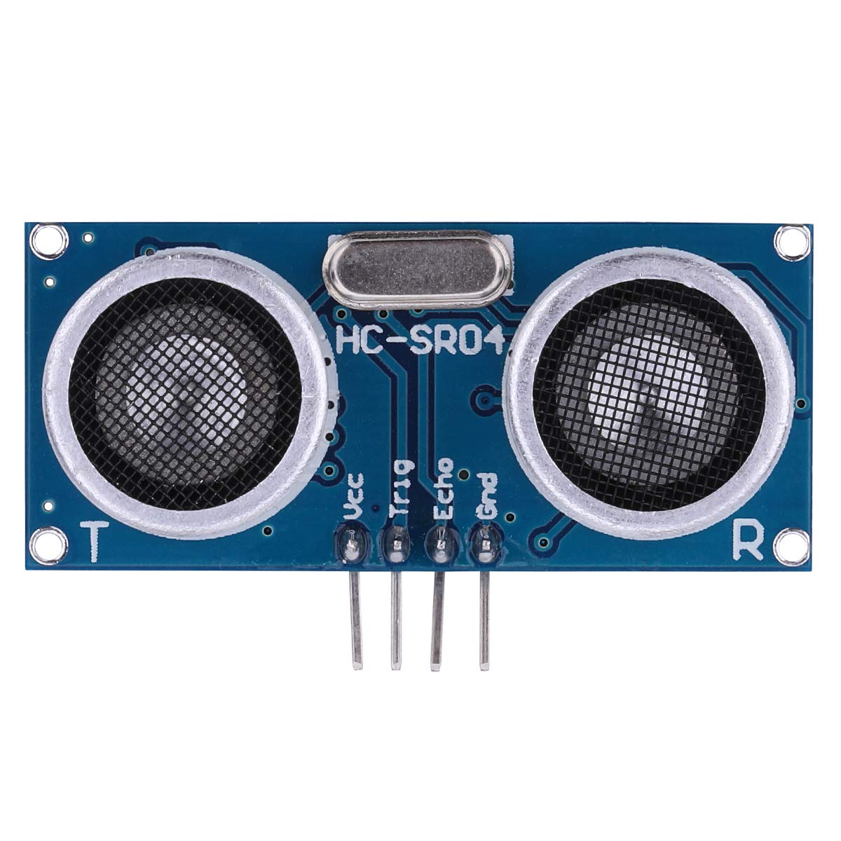
LEARN MORE ABOUT PARTS








Error Correction:
Step E) should direct to open/choose code for “wifi-lesson3” instead of “wifi-lesson2”.
hi, mark.g
you are right. It should be wifi-lesson3 in Step E. We just corrected the tutorial.
Thanks
For Step A, my program result stop as ” You’re connected to the network,press any key in APP to get remote data!”. I can not get the Step A result as you wrote.
My result is as below:
10:15:07.283 -> [Win APP to get remote data!
10:15:08.807 -> [WiFiEsp] Initializing ESP module
10:15:13.526 -> [WiFiEsp] Initilization successful – 1.5.4
10:15:13.590 -> Attempting to connect to WPA SSID: 23SS72BDFGDF
10:15:20.644 -> [WiFiEsp] Connected to 23SS72BDFGDF
10:15:20.678 -> You’re connected to the network,press any key in APP to get remote data!
I can not have IP address and target port mumber. Could you please confirm again that we can really get this result?