In this project, we will make a simple RFID (IC card) + IoT controlled security door system. We use Cell phone APP to send control signal through UDP protocol similar to Lesson 8.
Security Door normally is often opened by servo motor. To make things simple, we just use servo turning 180 degree to imitate door open and rotate back to 0 degree to imitate door close.
The whole procedure will be work as follows:
When an IC card detected by RC522 RFID module, OSOYOO Advanced Board for Arduino MEGA2560 will verify if its ID matches record.
If ID matches record, then servo turn 90 degree . Green LED turn on and Red LED turn off.
If ID does not match record, then, servo does not move, instead, the buzzer will alarm(you need use browser to turn off alarm from remote computer).
At any time, remote browser can open the door(servo rotate to 90 degree) or close the door (servo back to 0 degree) or turn off buzzer and monitor door status.
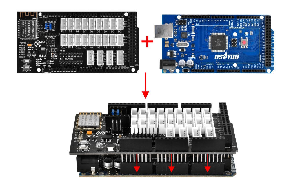
OSOYOO Advanced Board for Arduino MEGA2560 x 1
OSOYOO MEGA-IoT Extension Board x 1
Buzzer Module x 1
LED Module Green x 1, Red x 1
Micro Servo Motor x 1
RFID Module x 1
OSOYOO 3-Pin PnP Cable x 3
8pin 12cm Female to Female Cable x 1
USB Cable x 1
PC x 1
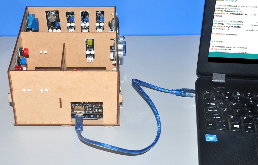
First, please plug OSOYOO MEGA-IoT Extension Board into OSOYOO Advanced Board for Arduino MEGA2560:
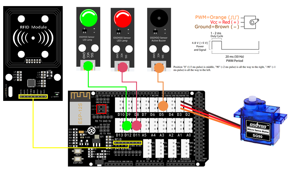
Then connect the modules with the OSOYOO MEGA-IoT Extension Board with three 3-pin PnP cables and one 8pin 12cm Female to Female Cable as below (Jumper Cap should connect ESP8266 RX with A8, TX with A9):
Green LED Module – D12
Red LED Module – D11
Buzzer Module – D5
Micro Servo Motor – D3
RFID Module – RFID
Notice: Shut off your battery or Unplug your power adapter when upload sketch code to OSOYOO Advanced Board for Arduino MEGA2560.
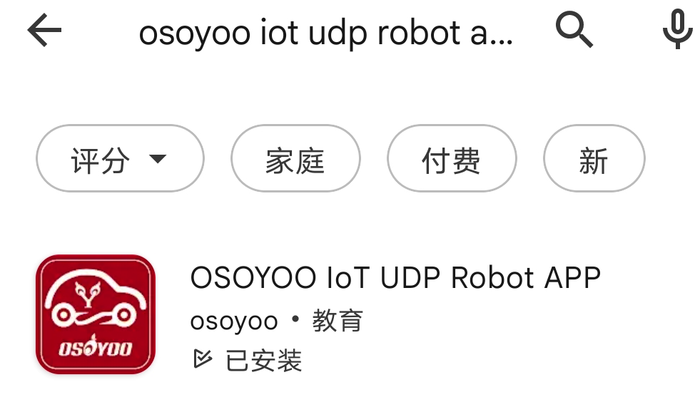
Step 1 Download OSOYOO IoT APP by searching OSOYOO IoT UDP robot car app from Apple Store(iPhone/iPad) or Google Play Store (Android device)
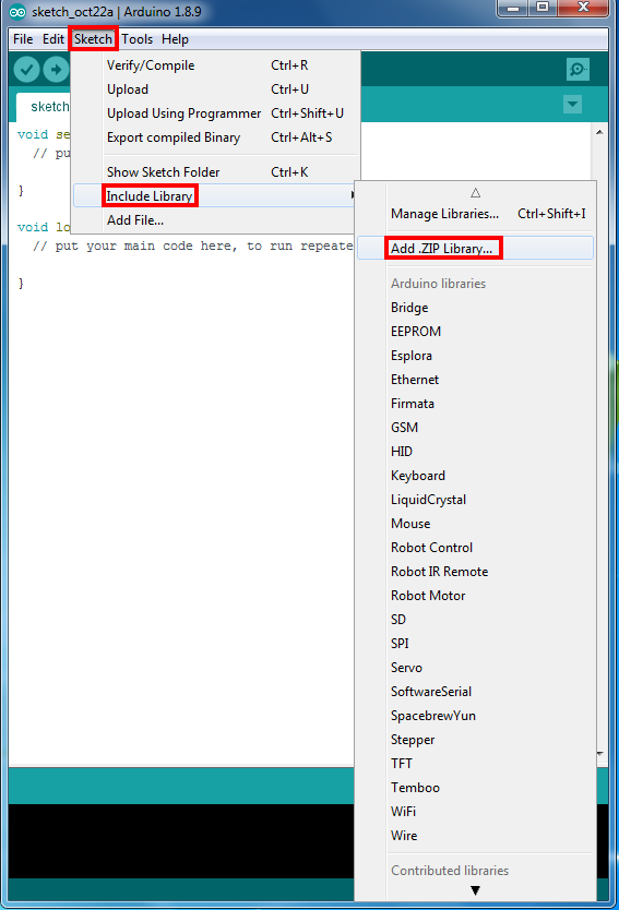
Step 2 WifiEsp Library Installation (if you have installed WifiESP library, please skip this step)
OSOYOO MEGA-IoT extension TX/RX pin to OSOYOO Advanced Board for Arduino MEGA2560 A9/A8 pin by default. So in sketch code, we need use Software Serial Port to communicate with ESP8266 (set A9 as TX and A8 as RX in softwareserial object).
Step 5 After above operations are completed, connect OSOYOO MEGA2560 Board to PC with USB cable.
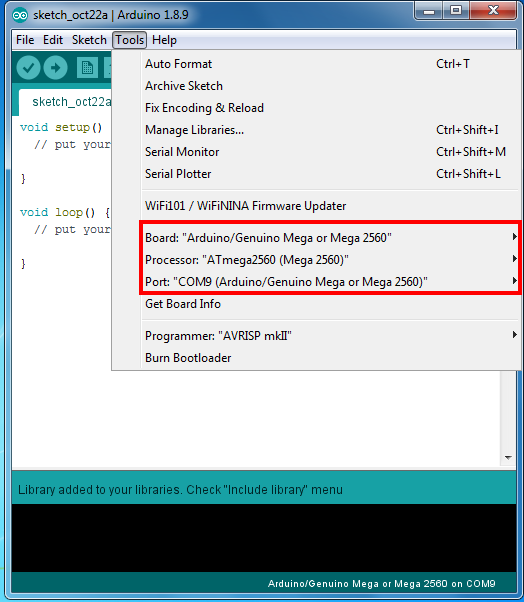
Step 6 IDE: Choose corresponding board type and port type for you project .
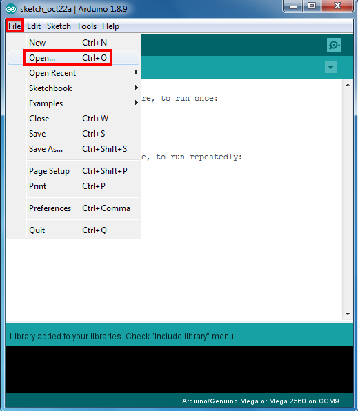
Step 7 IDE: Click file – Open, then choose code “smarthome-lesson16B.ino” in the folder, load up the sketch onto your OSOYOO Advanced Board for Arduino MEGA2560.
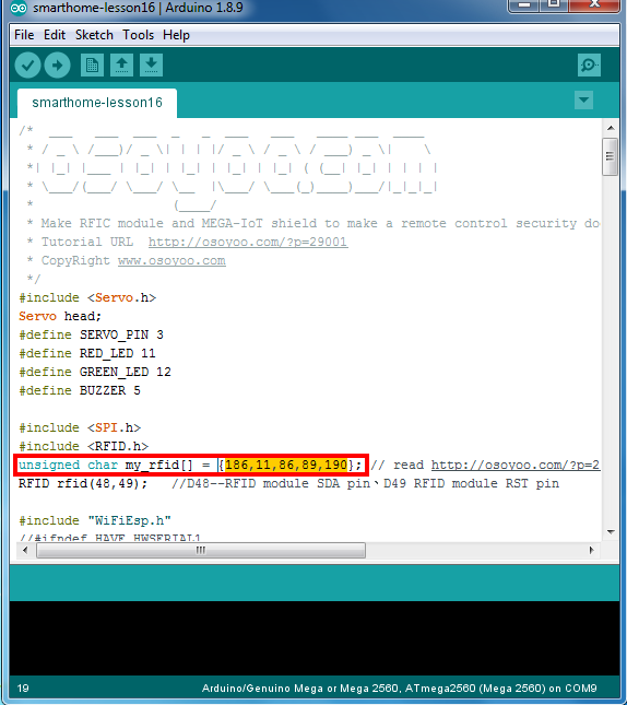
Remember to change the lines 19 of the code with the card number you got from Step 3): unsigned char my_rfid[] = {186,11,86,89,190}; // replace {186,11,86,89,190} with your own RFID card number
Note: In the sketch, find line 31 32 as following:
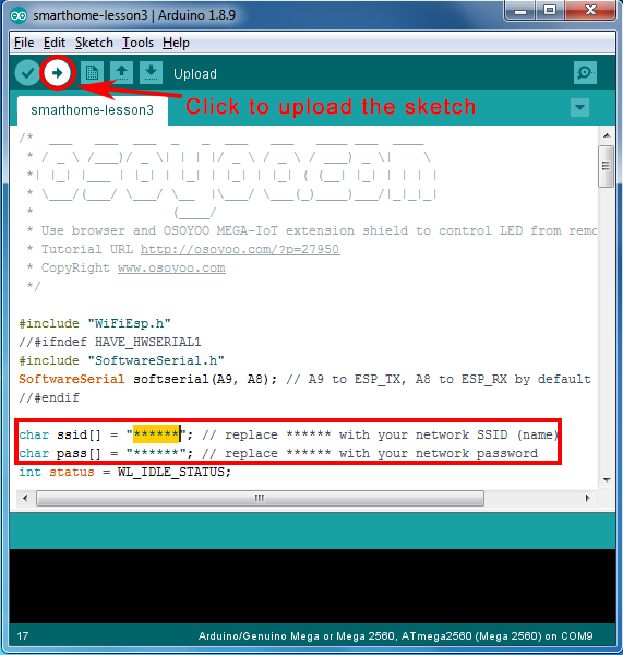
char ssid[] = "******"; // your network SSID (name)char pass[] = "******"; // your network password
please replace the ****** with your correct wifi SSID and password, otherwise your project can not connect to Internet.
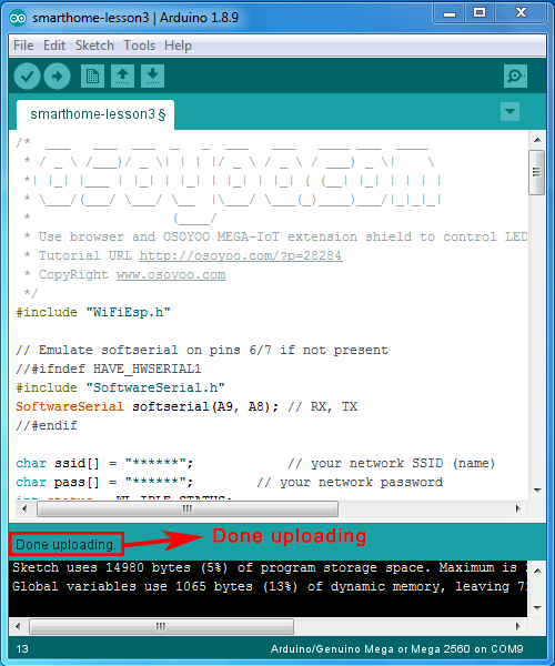
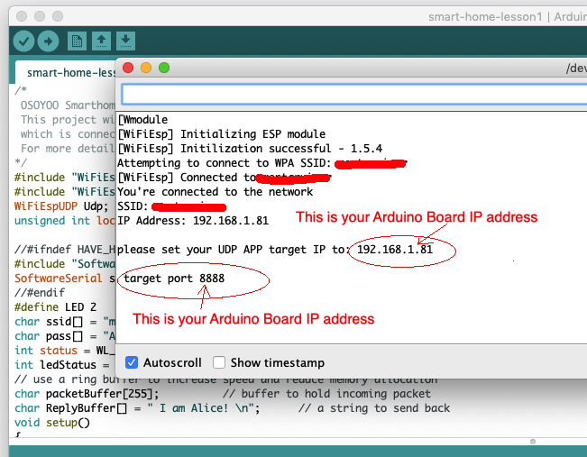
After loading the sketch to OSOYOO Advanced Board for Arduino MEGA2560 , open the serial monitor in the upper-right corner of IDE, you will see following result:
From the serial monitor, you can see the IP address of your MEGA2560 board in the read circle (in above picture, IP is 192.168.1.81), default port 8888, you need to set this IP address and port number in cell phone APP.
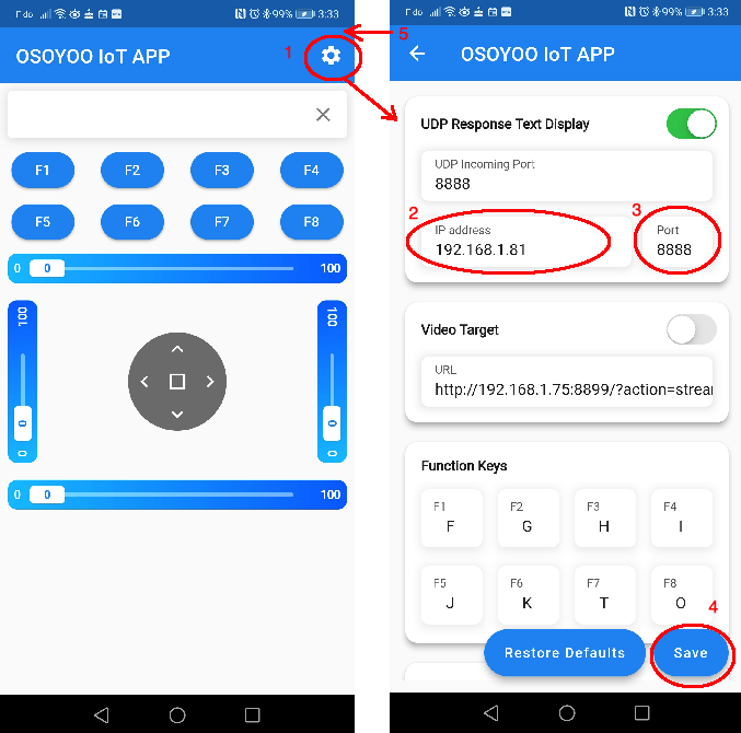
Now Open your Orange color APP and click Setting Icon, write IP address into the APP as following:
Running Result:
When you use an IC card which matches the value in code line 19, the door will open(servo rotate to 90 degree) and Green LED is ON.
When you use an IC card which does not match value of line 19, the door will NOT open and RED LED is ON. Buzzer will also alarm.
If you use Cell phone APP to control the Servo, the control method will be as following:
when you click ◄ button, the servo will point zero degree, Green LED is OFF.
Serial Monitor will show Close THE DOOR!
when you click ▲ button, the servo will point 90 degree, Green LED is OFF.
Serial Monitor will show Half Close THE DOOR!
when you click ► button, the servo will point 180 degree, Green LED is ON.
Serial Monitor will show OPEN THE DOOR!
when you click || button, the buzzer will turn off.