OSOYOO ESP8266 Module Purchase Link: https://osoyoo.store/products/arduino-esp8266-wifi-module-esp12s-arduino?_pos=1&_sid=ecd15bafc&_ss=r

In lesson 3 , we learned how Arduino and ESP8266 receive UDP command from a remote Cell phone APP.
In this lesson, we will use two Arduino board and two OSOYOO ESP8266 wifi Module to make an IoT Alarm system.
The first Arduino+ESP8266 module(device A) connects a PIR motion sensor and will send Alarm signal to another Arduino+ESP8266 when intruder is detected by PIR sensor.
The 2nd Arduino+ESP8266 module(device B) connects to a buzzer. It is keep listening to UDP packet(intruder signal) from the first system. Once intruder signal is received, Arduino will trigger buzzer to alarm.

- OSOYOO Basic board x 2
- OSOYOO ESP8266 WIFI Module x 2
- HC-SR501 PIR motion sensor x 1
- Active buzzer sensor module x 1

Device A Circuit Connection:
| OSOYOO WIFI Module |
OSOYOO Basic board |
| E_RX |
D5 |
| E_TX |
D4 |
| GND |
GND |
| VCC |
5V |
| HC-SR501 Sensor |
OSOYOO Basic board |
| Long Pin |
D3 |
| VCC |
5V |
| GND |
GND |
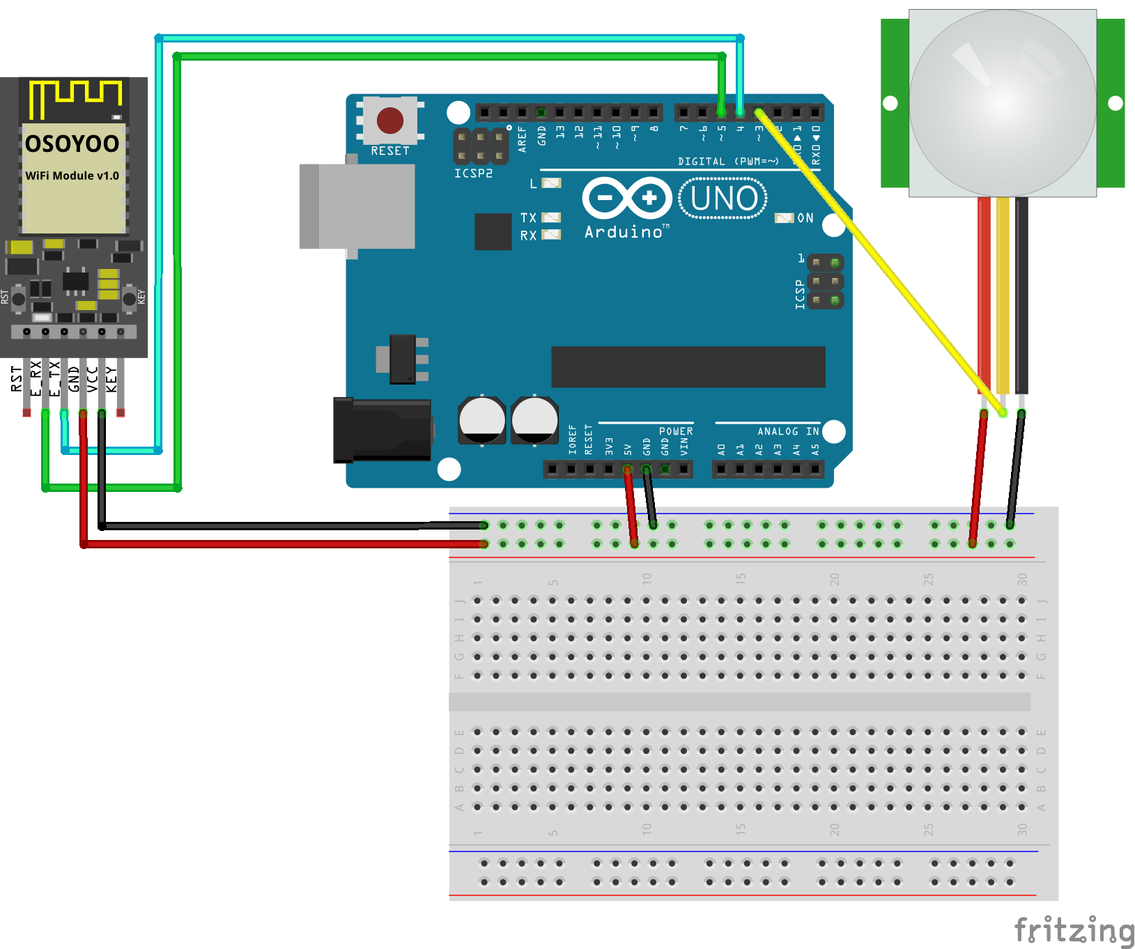
Device A circuit fritzing file download link https://osoyoo.com/driver/osoyoo-esp8266-module/lesson4/osoyoo-wifi-module-lesson4A.fzz
Device B Circuit Connection:
| OSOYOO WIFI Module |
Arduino UNO |
| E_RX |
D5 |
| E_TX |
D4 |
| GND |
GND |
| VCC |
5V |
| Buzzer |
Arduino UNO |
| Data |
D9 |
| GND |
GND |
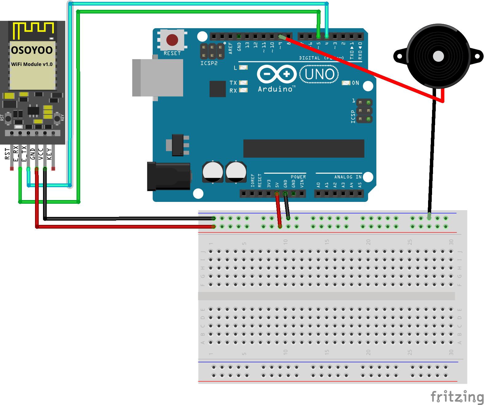
Device B circuit fritzing file download link https://osoyoo.com/driver/osoyoo-esp8266-module/lesson4/osoyoo-wifi-module-lesson4B.fzz

Step 1) Download the sketch file from:https://osoyoo.com/driver/osoyoo-esp8266-module/lesson4/esp8266-lesson4.zip
After unzip above file, you will see a folder “esp8266-lesson12” , enter this folder, you will see two sub-folders(buzzer and motionsensor).
Step 2)Connect Device B(buzzer system) to your PC and install software
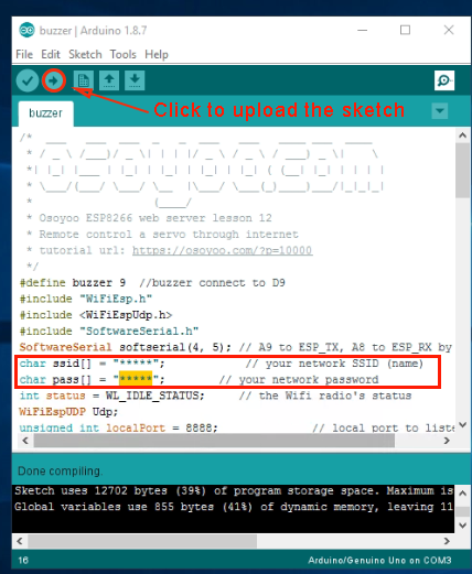
Enter buzzer folder and double click the buzzer.ino file, find following lines:
char ssid[] = "******"; // your network SSID (name)
char pass[] = "******"; // your network password
please replace the ****** with your correct wifi SSID and password, otherwise your project can
 not connect to Internet.
After changing the WIFI password, Upload above sketch to Arduino. Then open your serial monitor to check the device B(buzzer sensor) IP Address:
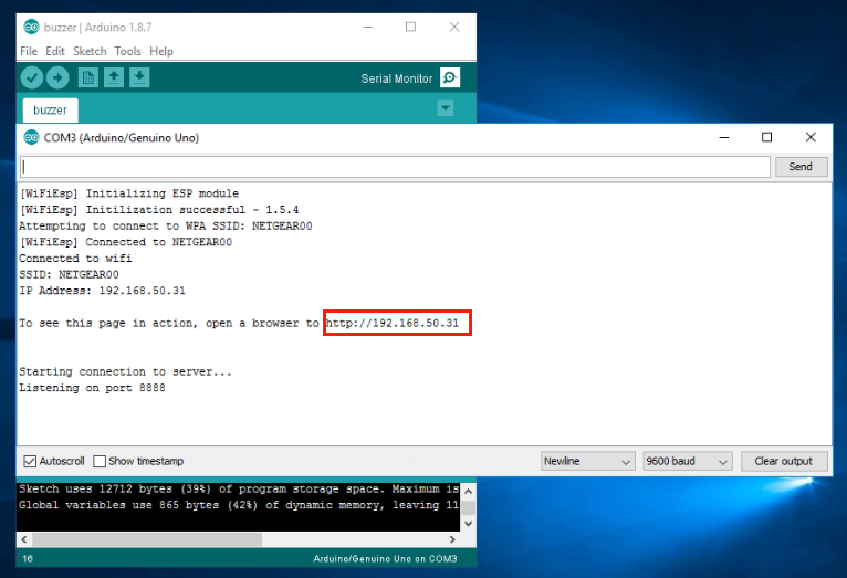
In above example, 192.168.50.31 is the IP address assigned by router to your buzzer Arduino.You have to write down this IP address in a paper. We need to use this IP address to change the sketch code in motionsensor.ino file. Then Device A can know where to notify Device B about intruder information.
Step 3) Now connect your Device A( PIR motion sensor system) to your PC, open the folder motionsensor and open the motionsensor.ino file, find following lins:
char ssid[] = "******"; // your network SSID (name)
char pass[] = "******"; // your network password
please replace the ****** with your correct wifi SSID and password, otherwise your project can not connect to Internet.
Then search following line:
byte remoteIp[] = { 10,0,0,244 }; //...
You need to change the line remoteIp[] variable , replace the IP address 10.0.0.244 with the Device B IP your recorded from Step 2. In our example, Step 2 shows device B ip address is 192.168.50.13, so we make the line to:
byte remoteIp[] = { 192,168,50,31 }; //…
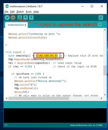
Then you can compile and upload the motionsensor.ino file to Arduino.
Test result:
Turn on power of both ESP8266 shield and Arduino boards . When you move your hand in front of the motion sensor, the remote buzzer will beep.


