In this lesson, you will learn how to make a small fan by Arduino and L293DD. At the end of this tutorial, you should be able to control spinning direction and speed.
Preparations
Hardware
Osoyoo UNO Board (Fully compatible with Arduino UNO rev.3) x 1
OSOYOO magic I/O Shield for Arduino x1
OSOYOO DC Motor with Fan x 1
OSOYOO Red button module x 1
OSOYOO Potentiometer Module x 1
3pin PnP cable x5
USB Cable x 1
PC x 1
Warning − Do not drive the motor directly from Arduino board pins. This may damage the board. Use a driver Circuit or an IC.
Software
Arduino IDE (version 1.6.4+)
About the DC Motor
Overview
A DC Motor is a type of electric motor that converts DC electrical power to mechanical power i.e. a DC supply is converted to rotation or movement. DC motors are one of the commonly used motors in different applications like electronic toys, power tools, portable fans, etc.
DC Motors are further classified in to different types like series, shunt and compound and each type is used in different areas of applications. Some DC motors are also used in Robotic and Industrial applications for their easy control and precision.
Since DC motors are generally associated with small to medium applications, where the system mainly consists of a Microcontroller as the main processing unit, controlling and driving a DC motor is very important. This is because, driving a motor directly using the microcontroller is not advised (sometimes not possible) as the current from the Microcontroller is very small (usually less than 30mA). Before you connect the circuit, check this link for how to power the dc motor correctly, thanks for the www.sharetechnote.com!
The DC motor (Direct Current motor) is the most common type of motor. DC motors normally have just two leads, one positive and one negative. If you connect these two leads directly to a battery, the motor will rotate. If you switch the leads, the motor will rotate in the opposite direction.
Features
Operating Temperature: -10°C ~ +60°C
Rated Voltage: 6.0VDC
Rated Load: 10 g*cm
No-load Current: 70 mA max
No-load Speed: 9100 ±1800 rpm
Loaded Current: 250 mA max
Loaded Speed: 4500 ±1500 rpm
Starting Torque: 20 g*cm
Starting Voltage: 2.0
Stall Current: 500mA max
Body Size: 27.5mm x 20mm x 15mm
Shaft Size: 8mm x 2mm diameter
Weight: 17.5 grams
Why Driving Motors with L293DD?
Driving electromotors needs a high current. In addition, spinning direction and speed are two important parameters to be controlled. These requirements can be handled by using a microcontroller (or a development board like Arduino). But there is a problem; Microcontrollers cannot provide enough current to run the motor and if you connect the motor to the microcontroller directly, you may damage the microcontroller. For example, Arduino UNO pins are limited to 40mA of current which is far less than the 100-200mA current necessary to control a small hobby motor. To solve this, we should use a motor driver. Motor drivers can be connected to the microcontroller to receive commands and run the motor with a high current.
L293DD is one of the most popular motor drivers to run DC motors with up to 1A current load.L293DD has 4 outputs which makes it suitable for 4-wire stepper motors. L293DD can also be used to drive servo motors. In this project, you will learn how to drive motors with L293 and Arduino UNO as the controller. To learn more about L293DD, do not miss this article: L293DD: Theory, Diagram, Simulation & Pinout.
Specifications
Supply Voltage Range 4.5V to 36V
600-mA Output current capability per driver
Separate Input-logic supply
It can drive small DC-geared motors, bipolar stepper motor.
Pulsed Current 1.2-A Per Driver
Thermal Shutdown
Internal ESD Protection
High-Noise-Immunity Inputs
Pin diagram of L293D
1,2EN: To activate the channel 1 and 2 we supply +5v to this pin. 3,4EN: To activate the channel 3 and 4 we supply +5v to this pin. Vcc1: Input voltage to derive the internal circuit (darligton array) = 4.5 to 36 v Vcc2: Supply/Output to appear at output = 4.5 to 36 v 1A: Channel-1 Input Pin 2A: Channel-2 Input Pin 3A: Channel-3 Input Pin 4A: Channel-4 Input Pin 1Y: Channel-1 Output Pin 2Y: Channel-2 Output Pin 3Y: Channel-3 Output Pin 4Y: Channel-4 Output Pin
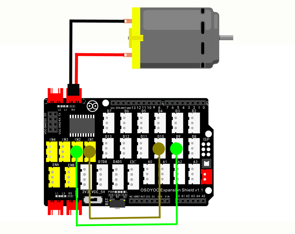
First, please plug OSOYOO Magic I/O shield into UNO board:
Then connect DC motor to the port L_1 interface of the Magic I/O shield, connect IN1 to D10, connect IN2 to D9. as below:
Code Program
After above operations are completed, connect the Arduino board to your computer using the USB cable. The green power LED (labelled PWR) should go on.Open the Arduino IDE and choose corresponding board type and port type for you project. Then load up the following sketch onto your Arduino.
intIN1=10;//define digital output pin D10intIN2=9;//define digital output pin D9voidsetup(){pinMode(IN1,OUTPUT);//set pin 10 as outputpinMode(IN2,OUTPUT);// set pin 9 as output}voidloop(){digitalWrite(IN1,LOW);digitalWrite(IN2,HIGH);}
Running Result
A few seconds after the upload finishes, you can see that the DC motor turns in one direction. To drive the motor in opposite direction you just need to put HIGH instead of LOW and vice versa.
Control the DC Motor direction and speed by Arduino
In this example, we will show how to control the direction and speed of a fan by using the OSOYOO Expansion Shield and the Arduino board.
Connection
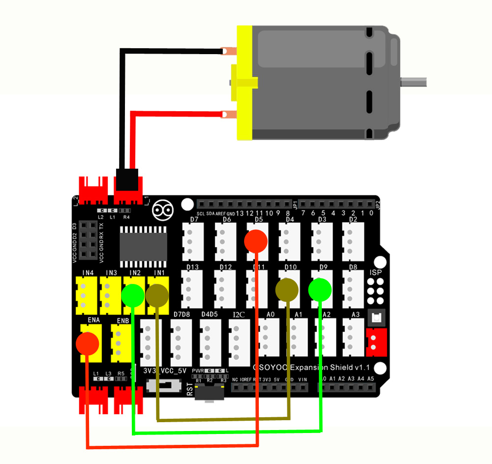
Connect DC motor to the port L_1 interface of the Magic I/O shield, connect IN1 to D10, IN2 to D9, ENA to D5. as below:
Code Program
After above operations are completed, connect the Arduino board to your computer using the USB cable. The green power LED (labelled PWR) should go on.Open the Arduino IDE and choose corresponding board type and port type for you project. Then load up the following sketch onto your Arduino.
#defineENA5#defineIN110#defineIN29/*motor FAN control*/voidgo_Advance(void)//Forward{digitalWrite(IN1,LOW);digitalWrite(IN2,HIGH);analogWrite(ENA,255);//SPEED 255(YOU CAN SET IT FROM 0~255);}voidgo_Back()//Reverse{digitalWrite(IN1,HIGH);digitalWrite(IN2,LOW);analogWrite(ENA,100);//SPEED 100(YOU CAN SET IT FROM 0~255); }voidstop_Stop()//Stop{digitalWrite(IN1,LOW);digitalWrite(IN2,LOW);analogWrite(ENA,0);//SPEED 0(YOU CAN SET IT FROM 0~255);}voidsetup(){pinMode(IN1,OUTPUT);pinMode(IN2,OUTPUT);pinMode(ENA,OUTPUT);go_Advance();//Forwarddelay(4000);//DELAY FOR 4 seconds.go_Back();//Reversedelay(2000);//DELAY FOR 2 seconds.stop_Stop();//Stop}voidloop(){}
Running Result
A few seconds after the upload finishes, the fan runs at full speed for 4 seconds, then the fan will reverse at a slower speed for 2 seconds and then stop
Manually control the rotate direction and speed of the Mini Fan
In this example, we use a potentiometer to control the speed of the motor and a push button to control the direction. Moving forwards, this hardware and code can be adapted to make a small driving robot.
Connection
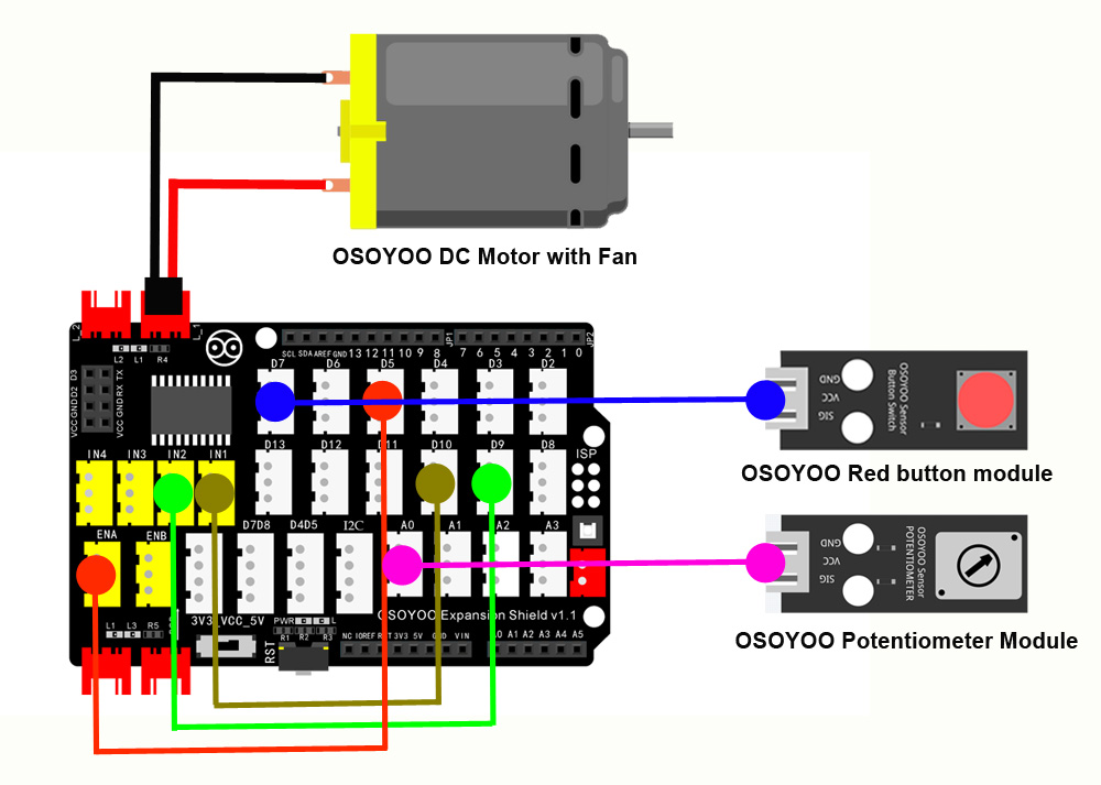
Connect DC motor to the port L_1 interface of the Magic I/O shield, connect IN1 to D10, connect IN2 to D9, ENA to D5, Connect OSOYOO Red button module to the port D7 of the Magic I/O shield with 3-pin PNP cables, Connect OSOYOO Potentiometer Module to the port A0 of the Magic I/O shield with 3-pin PNP cables. as below:
Code Program
After above operations are completed, connect the Arduino board to your computer using the USB cable. The green power LED (labelled PWR) should go on.Open the Arduino IDE and choose corresponding board type and port type for you project. Then load up the following sketch onto your Arduino.
intswitchPinFwd=7;//Input from the switch when in the Forward positionintpotentiometerIn;//variable to hold the potentiometer inputintfwdPin=10;//Logic level output to the H-Bridge (Forward)intrevPin=9;//Another logic level output to the H-Bridge (Reverse)voidsetup(){// put your setup code here, to run once:pinMode(switchPinFwd,INPUT_PULLUP);pinMode(fwdPin,OUTPUT);//Set the forward pin to an outputpinMode(revPin,OUTPUT);//Set the forward pin to an output}voidloop(){// put your main code here, to run repeatedly:potentiometerIn=analogRead(A0);intoutput=potentiometerIn/4;//divide the potentiometer input by 4 so it can be used in the AnalogWrite functionif(digitalRead(switchPinFwd)==HIGH)//Check to see if the pin is high or low{//If the pin is HIGH, it must be set to forwardanalogWrite(fwdPin,output);//Output our potentiometer value on the forward pin.}else{//Otherwise the switch must be set to ReverseanalogWrite(revPin,output);//Output our potentiometer value on the forward pin.}delay(25);}
Running Result
A few seconds after the upload finishes, plug the motor power supply in so the motor has power and after a few seconds try adjusting the potentiometer to adjust the motor speed. When changing directions, ensure the motor is stopped as it is not a good idea to reverse the polarity of a motor while running. Going forward, code could be added to this to prevent the user from changing direction unless the throttle is at 0.