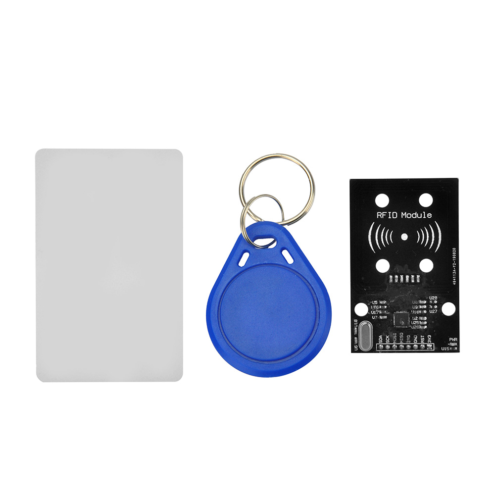
In this lesson, we will show how to use the Osoyoo IoT Kit to build an RFID access control system. Before starting this lesson, you can get more information about the RFID module from this link.
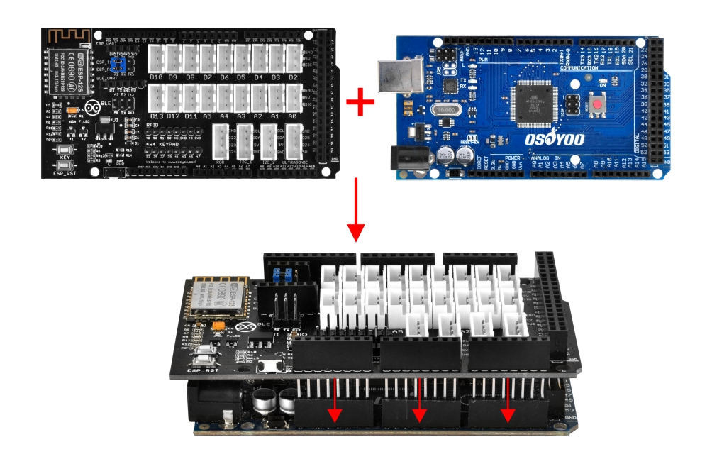
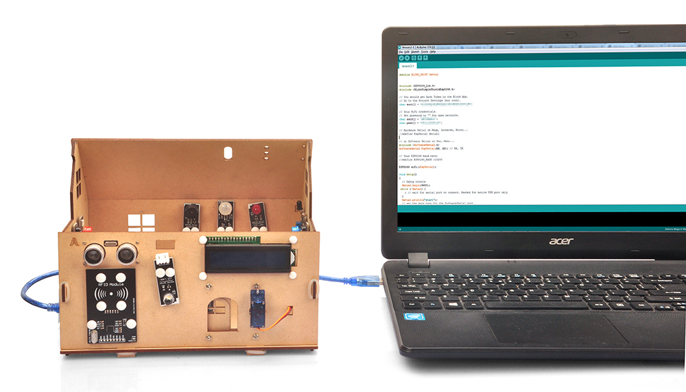
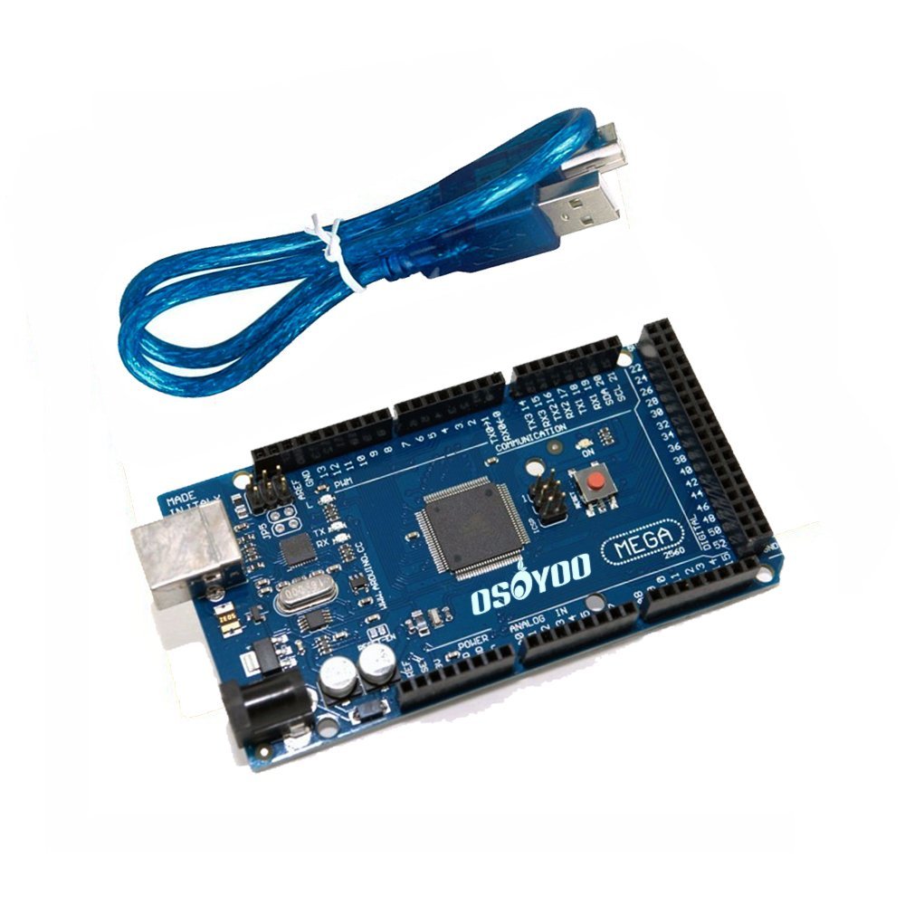
Step 2 After above operations are completed, connect OSOYOO MEGA2560 Board to PC with USB cable.
Notice: Shut off your battery or unplug your power adapter when upload sketch code to Arduino.
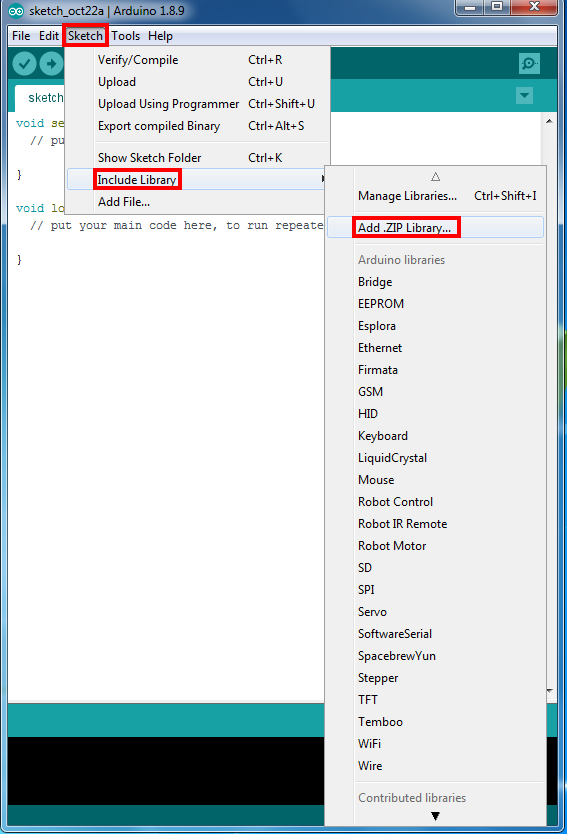
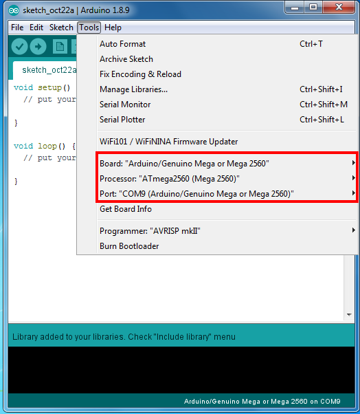
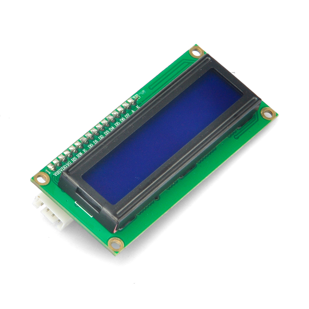
Step ii) Open Arduino IDE: Choose corresponding board type and port type for your project.
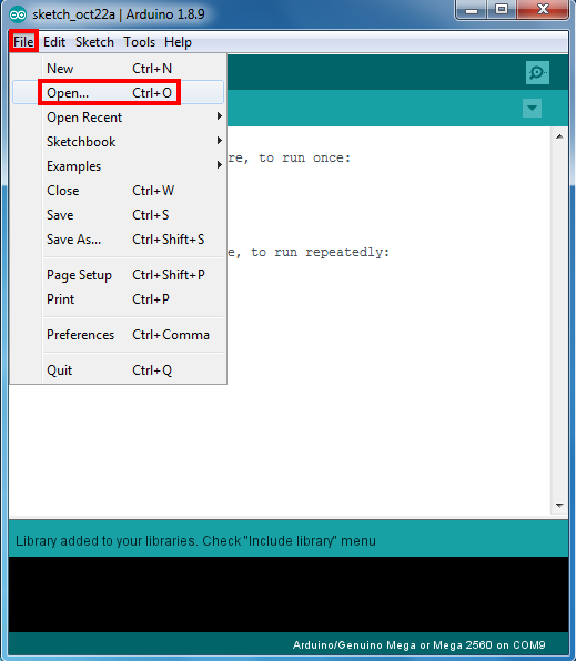
Step iii) Arduino IDE: Click file – Open, then choose code in the folder, load up the servo_config.ino sketch onto your Arduino.
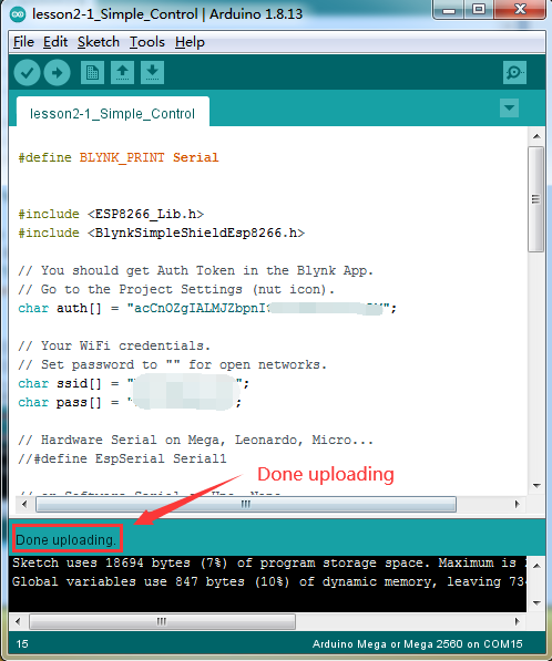
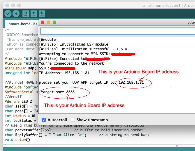
Upload the sketch to the board. Wait until you see something like this:
Done uploading
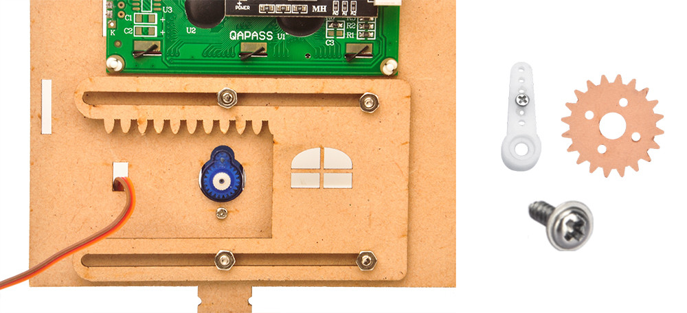
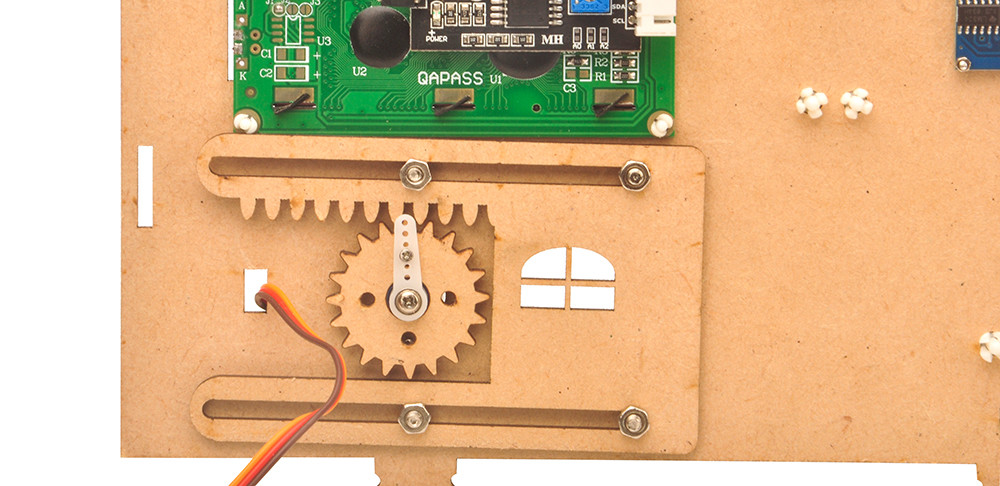
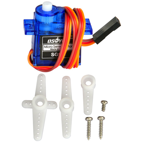
Step iv) After upload the code, the servo will turn to 0 degree position, now we install the wooden gear and the white fixed arm:
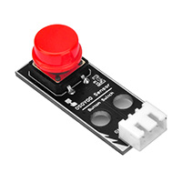
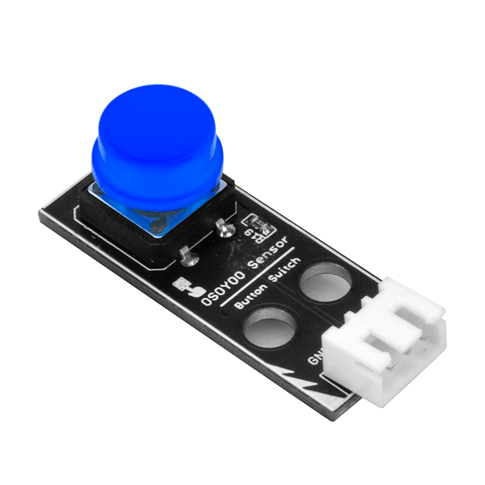
Step 5 Press the button, the door can be simulated to open, when released, the door can be simulated to close.
After Servo test and installation is completed, we can go to next task. If the door can not be close or open properly, please adjust the servo arm beginning position accordingly.
After completing the above steps and uploading the code, open the IDE serial monitor, we need to find out your RFID card number.
To this, pick a white or blue RFID card and tap it in the RFID sensor, you will see something as following:
RFID START!Find the card!Card type: UnknownThe card's number is : 71ba2f2eca
71ba2f2eca ID is unknown.
In the above example, 71ba2f2eca is your RFID number just tapped. Now in code line 15, we need to change variable marystr from 33cd216fb to 71ba2f2eca:
String marystr="33cd216fb"; //change 33cd216fb with your test ID card
After changing, the line 15 will be as following:
String marystr="71ba2f2eca";
In the same way, you can add or modify your card information at will, and finally, re-upload the code to the Arduino and continue the experiment.
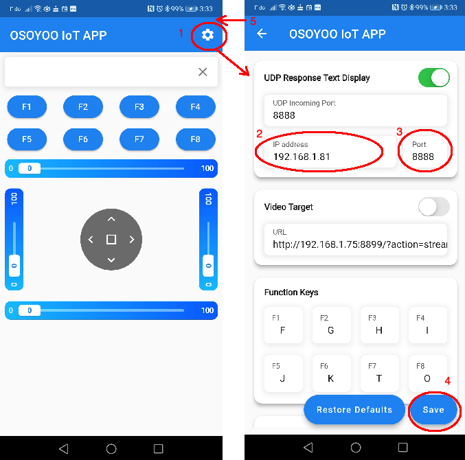
Step 2):Make sure your Cell phone is in the same Local Network of Arduino. Open the APP, click Settings, enter your Arduino IP address from Step F and Port to 8888 in settings:
Now you can use the test RFID card to tap the RFID sensor, the door will open for 1 seconds then close. Your APP will show “Mary at the Door”
If you click the F8 key in APP, you can also open the door. APP will show “Door is open by APP”
You can also push the button to open the door.
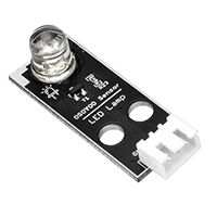
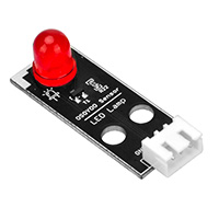
Each time when the door is open, the LED will turn on. After the door is close, LED will turn off.