Introduction
Gyro is one of the most commonly used electronic component in human society. From large devices like rockets, satellites, and torpedoes, to small ones like smartphones and toy drones, we all use gyros.
In this course, we will learn how to program a gyroscope with Arduino to optimize the OSOYOO Robot Car’s performance.
Hardware Required by this project:
1)OSOYOO Espro All-in-one ESP32 motor controller (fully support Arduino Programming IDE)
2)MPU6050 Gyro Module:
Shopping Link: https://osoyoo.store/products/mpu6050-gyroscope-module
3)Robot car chassis system including: Motors+ wheels+Chassis+Battery , you can make to order a customized chassis system in following link:
https://osoyoo.com/osoyoo-general-robot-car-make-to-order/
Hardware Installation:
Simply insert your MPU6050 module into the Espro board gyro slot. Then install the Espro board onto the chassis, insert the left motor onto the K3/K4 slot. Insert to right motor to K1/K2 slot in Espro board.
Install Arduino Libraries
We need following libraries Adafruit MPU6050/Adafruit Unified Sensor library and PID library to run the sample code of this lesson. There are two methods to install these two libraries;
Method 1 : Install from Arduino IDE
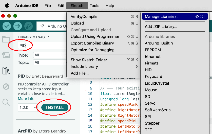
In Arduino IDE top menu -> Sketch ->Include Library->Manage Libraries
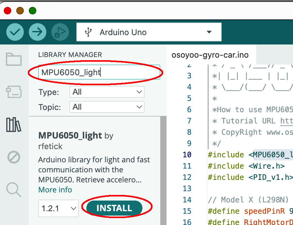
Search MPU6050_light , you will find a library “MPU6050_light by rfetick”,
Click Install, then Install ALL to install MPU6050_light library.
Similarly, install PID library from Arduino IDE as following :
Method 2: Install from Zip File
Download 6 zip files from following links:
https://osoyoo.com/driver/2wd/MPU6050_light.zip
https://osoyoo.com/driver/2wd/PID.zip
Once you have downloaded above 6 zip files, do NOT unzip them, open Arduino IDE ->Sketch ->Include Library ->Add Zip Library. Then upload above 6 zip files to Arduino One by One.
Run Sample Code :
Step 1)Download https://osoyoo.com/download/osoyoo-gyro-car2.zip , unzip the file and uploaded osoyoo-gyro-car.ino file to Arduino IDE
In Serial Monitor, set baud rate to 9600, then you should see:
MPU6050 Found!
Congrats! This means Arduino detects MPU6050 and you can put the car in the ground and test the performance.
Now you can put the car onto the ground, turn on the power. You will see the car will stay freeze for a while waiting the Arduino to initialize the gyro. Then the car will move straight forward . If you use your foot to force the car change direction, the car will automatically go back to its original direction.
A Brief Explanation to the Principle and Arduino code
1)How does the Move() function control the car’s movement and steering?
The OSOYOO robot car used in this lesson utilizes differential steering. The move(speedL, speedR) function has two parameters, speedL and speedR, which represent the rotational speed of the car’s left and right wheels, respectively. The speed value ranges from -255 to +255, where a positive value indicates forward rotation and a negative value indicates backward rotation. For example, move(-50, 100) means the left wheel rotates backward at a speed of 50, while the right wheel rotates forward at a speed of 100. In this case, the car should make a sharp left turn.
1)MPU6050 Coding Introduction
After initialization, the gyroscope MPU6050 can consistently determine its orientation relative to its starting direction. When our robot car moves and deviates from this initial direction, the MPU6050 reports the amount of this deviation back to the Arduino.
In our code, the Direction variable represents the car’s orientation at the moment it was placed on the ground (we assume it’s facing forward, so we set Direction to 0).
After the calculations in the first few lines of the loop() function, we obtain the car’s current orientation in the currentAngle variable on line 129.
2)Introduction about PID and Code:
The Big Idea: What is PID?
Imagine you are driving a car and your goal is to keep it perfectly in the center of your lane. That’s what we’re asking our robot to do: stay on the “straight ahead” line.
PID is a control algorithm that acts like a smart, attentive driver. It continuously asks three questions to decide how to steer:
- P (Proportional): How far am I from the center of the lane right now?
- I (Integral): Have I been consistently off-center for the past few moments?
- D (Derivative): Am I swerving towards or away from the center too quickly?
By combining the answers to these three questions, the PID controller makes a smooth and efficient steering correction.
How the PID Function Works in Our Code
Let’s connect this theory directly to the PID_v1.h library and your code.
1. Initialization (in setup()):
// We tell the PID controller what to watch and what to control.
PID myPID(&Input, &Output, &Setpoint, Kp, Ki, Kd, DIRECT);

Direction = 0; // Our TARGET is to have an angle of 0 degrees.
myPID.SetMode(AUTOMATIC); // Turn on the controller.
&Input: This is a pointer to our sensor reading. In our code, Input is currentAngle. The PID controller will constantly read this value.&Output: This is a pointer to our result. The PID controller will write its final calculated correction value into the Output variable.&Direction: This is a pointer to our target. We want to stay straight, so we set this to 0.
2. The Magic (in loop()):
// 1. We get the sensor reading and put it into the Input variable.
Input = currentAngle;

// 2. We call the compute function. This is where the PID magic happens!
myPID.Compute();

// 3. We use the result to control the motors.
int speedL = baseSpeed - Output;
int speedR = baseSpeed + Output;
move(speedL, speedR);
The myPID.Compute() function does all the hard work internally. Every time it’s called (the library handles the timing based on SetSampleTime), it:
- Reads the value from the
Input variable (currentAngle).
- Calculates the error:
error = Direction - Input.
- Calculates the Proportional term (
Kp * error).
- Calculates and adds the Integral term (
Ki * accumulated_error).
- Calculates and adds the Derivative term (
Kd * rate_of_error_change).
- Sums them all up to get the final correction value.
- Writes this final value into the
Output variable.
So, if Output is +15, it means the robot needs a correction of “15 units.” We apply this by slowing down one motor (baseSpeed - 15) and speeding up the other (baseSpeed + 15), causing the robot to turn and reduce its error. If the robot is perfectly straight, Input will be 0, the error will be 0, and Output will be 0, so both motors will run at baseSpeed.
How to Adjust Kp, Ki and Kd value to make car moving stable
- MUST DO: Modify your code to set
Ki = 0.0 and Kd = 0.0.
- Find a
Kp value that is stable and doesn’t oscillate (or barely oscillates). This will likely be lower than 1.5.
- (Optional but recommended) Add a
deadband of around 0.5 degrees to your loop to ignore sensor noise.
- Once
Kp is stable, slowly add Kd to dampen any remaining overshoot.
- Finally, slowly add
Ki to eliminate any long-term, steady drift.


