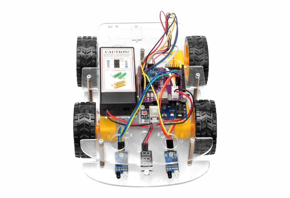
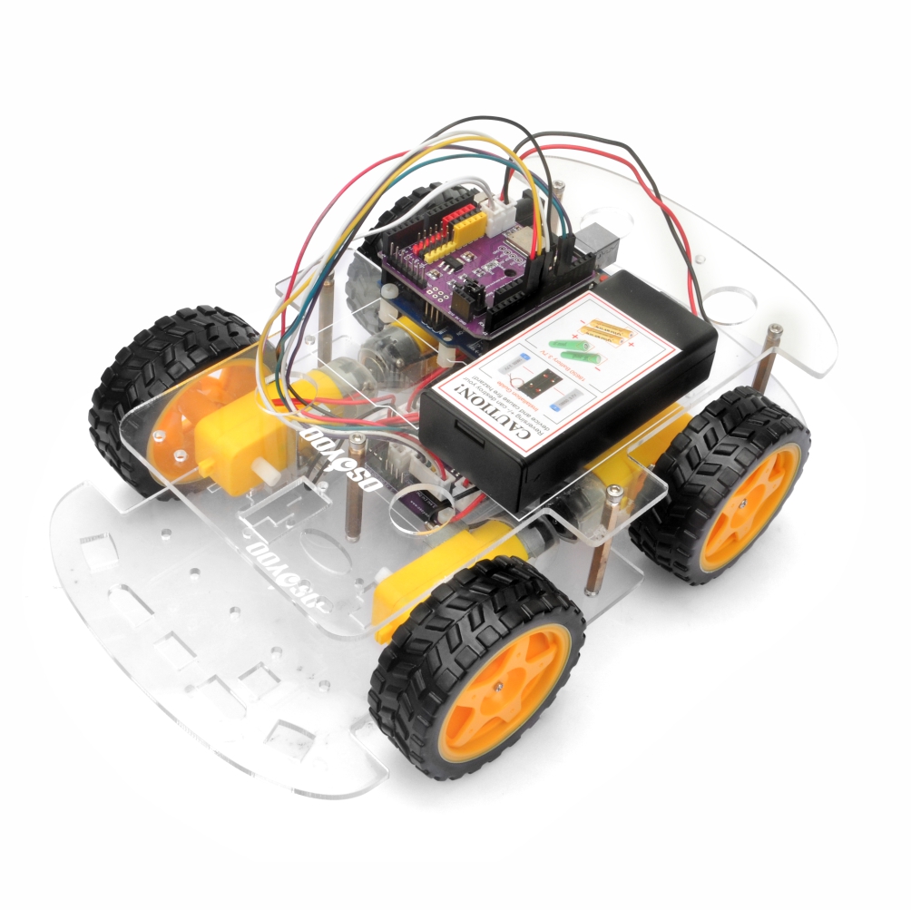
In this lesson, you will transform your OSOYOO V3 Robot Car into an intelligent object-following robot. By using two infrared distance sensors mounted at the rear of the vehicle, the robot can detect nearby objects and automatically adjust its movement to follow them.
This project introduces the fundamentals of sensor-based autonomous navigation and demonstrates how robots can interact with their environment using real-time sensor feedback.
Before starting this lesson, please make sure you have successfully completed Lesson 1: Basic Robot Car Assembly.
After completing this lesson, you will learn how to:
Install and configure infrared distance sensors
Read digital sensor signals in Arduino
Implement basic autonomous navigation logic
Use sensor feedback to control motor movement
2Parts and Devices
Make sure you have all the following parts ready before you begin.
No.
Picture
Device
Qty.
Accessories
Link
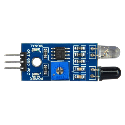
1
IR Distance Sensor
2
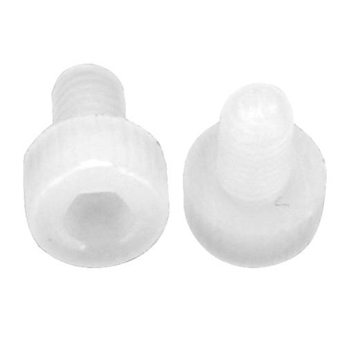
M3 Plastic Screw x 2
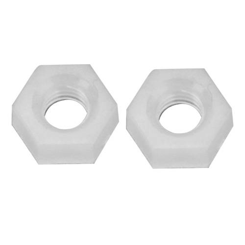
M3 Plastic Nut x 2
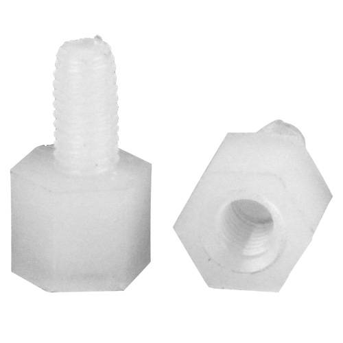
M3 Plastic Pillar x 2
The robot uses two infrared distance sensors to detect objects positioned behind the vehicle.
Each sensor continuously checks whether an object is within its detection range. The Arduino controller reads the sensor outputs and determines how the robot should move:
Left Sensor
Right Sensor
Robot Action
Detected
Detected
Move Forward
Detected
Not Detected
Turn Left
Not Detected
Detected
Turn Right
Not Detected
Not Detected
Stop
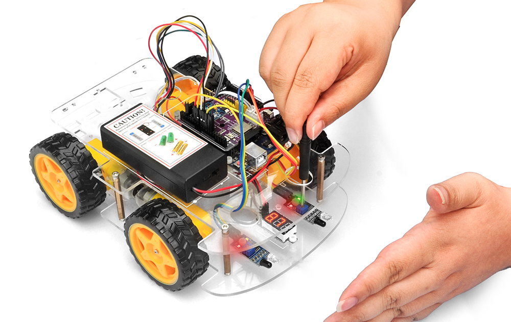
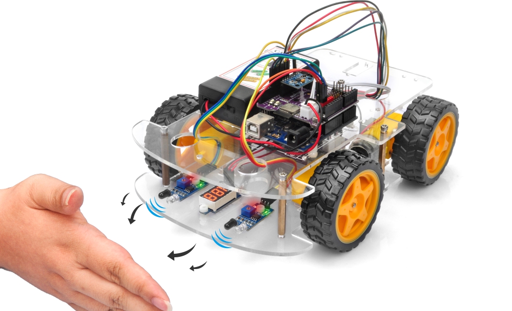
Because the sensors are installed at the rear of the robot, the vehicle appears to “follow” your hand or another object as you move it.
4Hardware Installation
Step 1: Assemble the basic robot car according to Lesson 1. If your robot has already completed Lesson 2, just keep it as is.
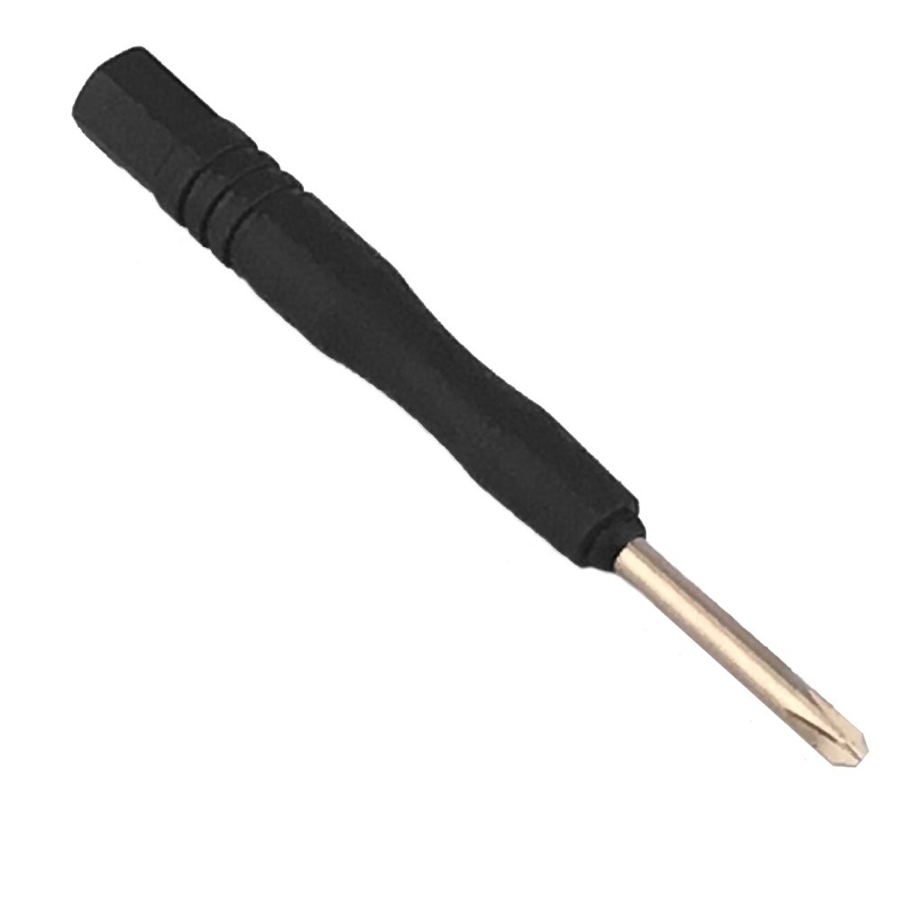
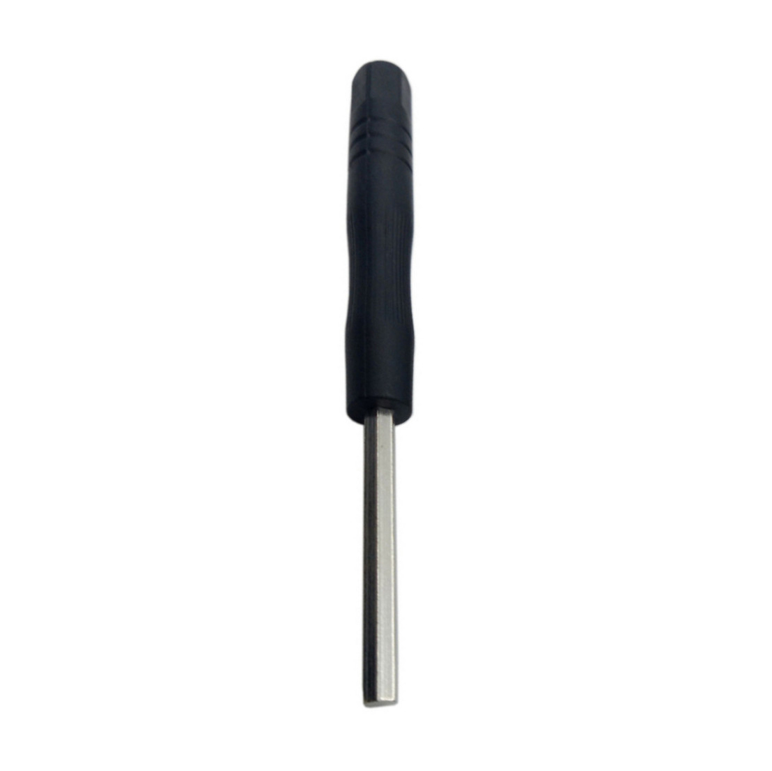
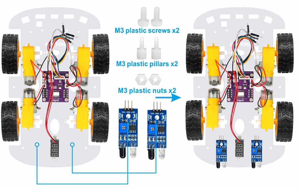
Step 2: Remove the M3 hex screws on the upper chassis. Attach two infrared distance sensors to the rear section of the lower chassis using M3 plastic screws, plastic pillars, and plastic nuts.
Important:
The sensors should face outward.
Make sure both sensors are aligned horizontally.
Avoid blocking the transmitter and receiver lenses.
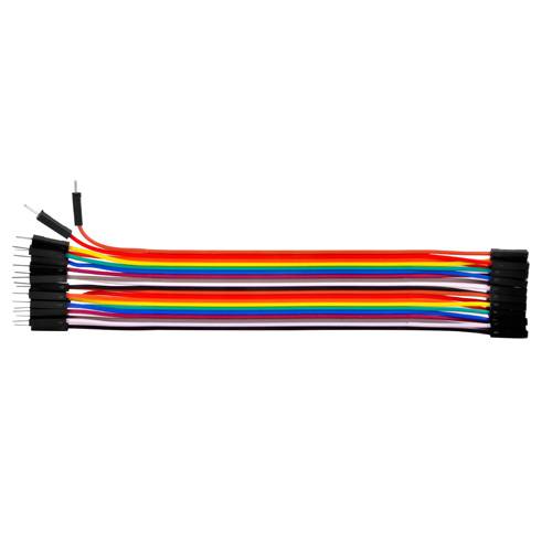
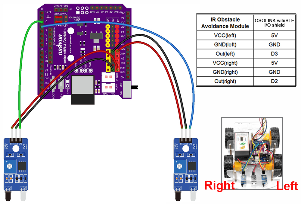
Step 3: Connect the two IR distance sensors according to the wiring diagram provided below:
⚠️ 1. Do not disconnect any existing wiring installed in Lesson 1. 2. Insert the sensor wires securely to prevent intermittent signal loss during operation.
Step 4: Reinstall the upper chassis and tighten all mounting screws.
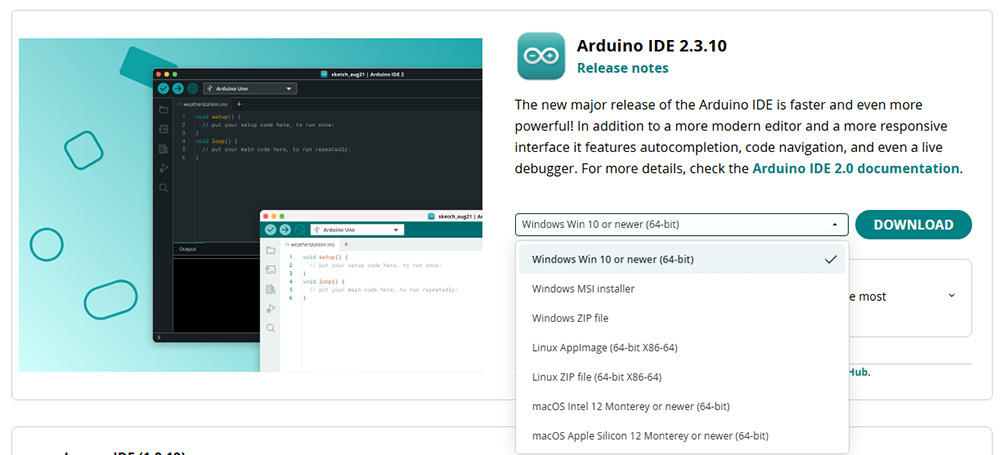
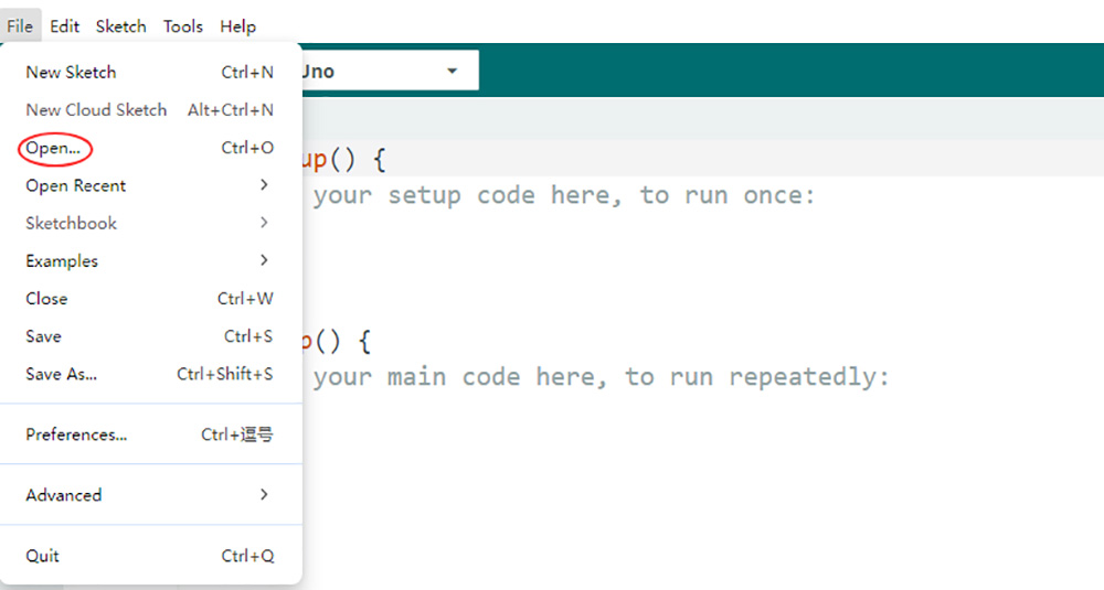
2. Download the Sample Code: Download the sample code for Lesson 3 here. Extract the archive to get the file v3car-lesson3.ino inside the folder v3car-lesson3. Open the sketch in the Arduino IDE.
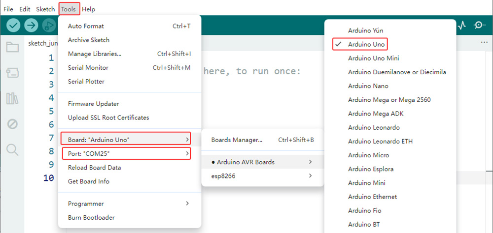
3. Board and Port Selection: Connect the OSOYOO Basic Board (compatible with Arduino UNO) to your computer via a USB cable (Important: make sure the robot car’s power switch is OFF and the battery is disconnected before connecting the board to your PC). Launch the Arduino IDE, go to Tools > Board and select Arduino Uno, then go to Tools > Port and select the correct serial port. If you are unsure which port to use, check your operating system’s device manager.
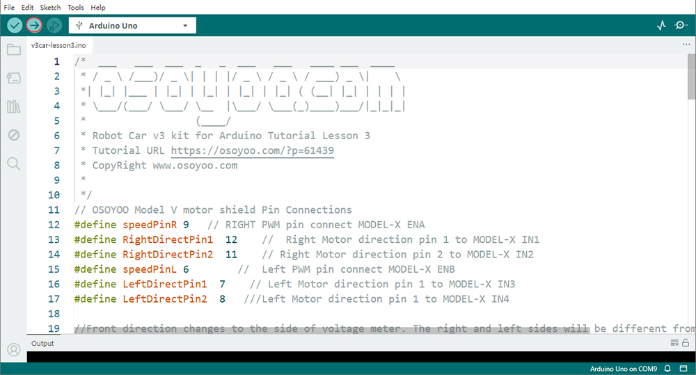
4. Upload the Code: Click the “Upload” button (right arrow icon) to compile and transfer the sketch to the OSOYOO Basic Board.
6Sensor Calibration
Before testing, adjust the sensitivity of both IR distance sensors.
Calibration Procedure
Power on the robot and hold it in your hand.
Place your hand approximately 10 cm in front of the sensor.
Slowly rotate the onboard potentiometer.
Watch the indicator LED.
Correct Adjustment
Object detected → Signal LED (green LED) ON
No object detected → Signal LED (green LED) OFF
7Test the Car
After calibration, turn on the robot and place an object or your hand behind it. Slowly move the object and observe the robot’s response.
Expected Behavior:
Both sensors detect the object → Robot moves forward
Only the left sensor detects the object → Robot turns left
Only the right sensor detects the object → Robot turns right
No object detected → Robot stops
Note:
1. Since the IR sensors are mounted at the rear of the vehicle, the robot’s movement logic is opposite to many other lessons.
2. This project only supports forward movement, left turns, and right turns. Reverse movement is not implemented in this lesson.
8Troubleshooting
1. Robot Does Not Move
Check:
Battery voltage
Motor wiring
Sensor connections
Program upload status
2. Robot Always Moves Forward
Possible causes:
Sensor sensitivity too high
Ambient infrared interference
Incorrect wiring
Try recalibrating the sensors.
3. Robot Turns Randomly
Check:
Sensor alignment
Loose jumper wires
Uneven sensor sensitivity settings
Both sensors should be adjusted to similar detection distances.