OSOYOO
OSOYOO ESP32-S3 IO Breakout Board
Product Introduction & Arduino Tutorial | Version 1.0
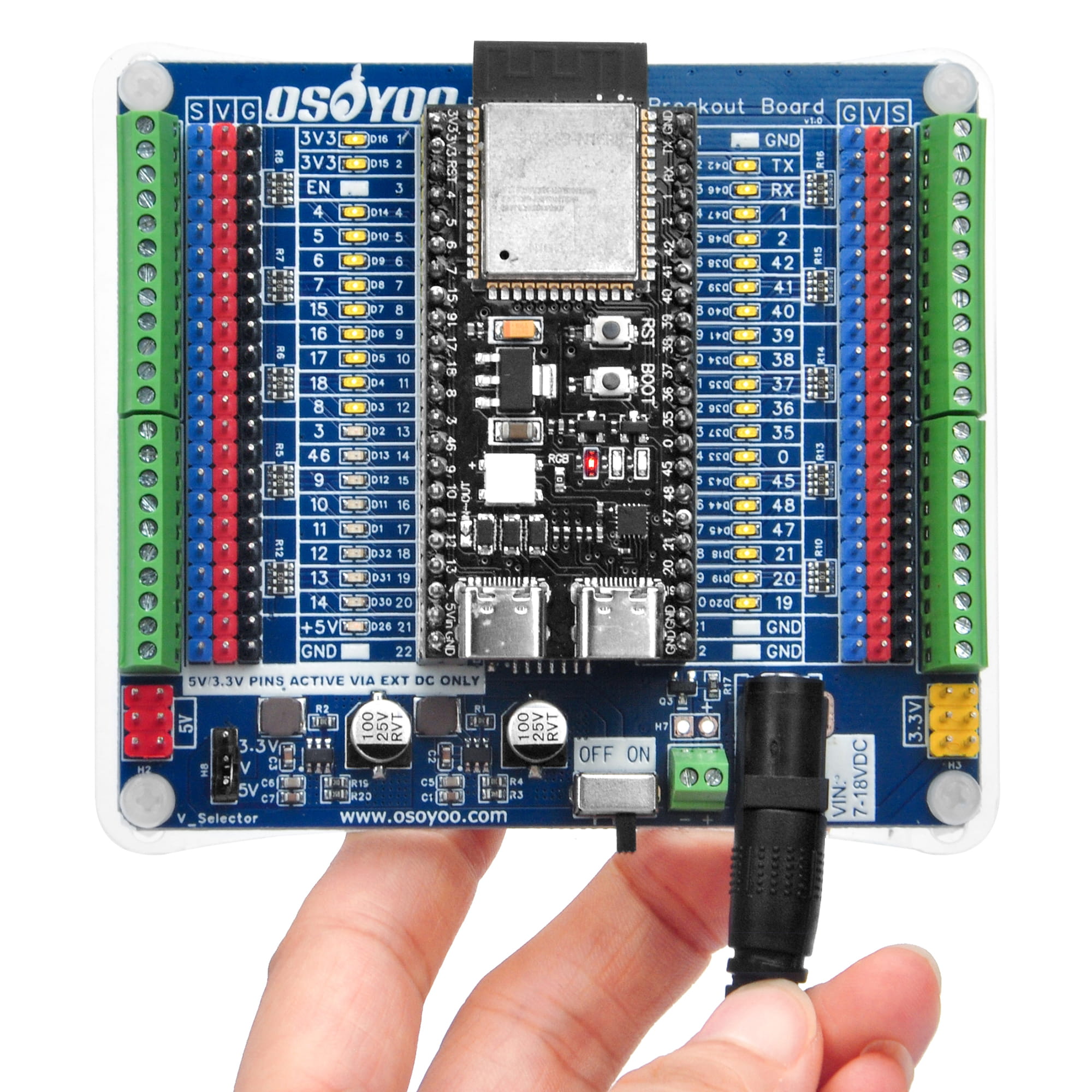
Fig 1 – OSOYOO ESP32-S3 IO Breakout Board with an ESP32-S3 development board inserted
1. Overview
The OSOYOO ESP32-S3 IO Breakout Board is a purpose-built GPIO expansion and hardware debugging platform for the ESP32-S3 series of microcontrollers. It provides structured, labelled access to every GPIO pin, real-time LED status visualization for each pin, dual regulated power outputs, and flexible screw-terminal peripheral connections — accelerating development cycles and eliminating the messiness of a traditional breadboard setup.
The board’s 2×22P female socket accepts the vast majority of commercially available ESP32-S3 development boards. The socket span accommodates MCU modules with pin-row spacing of 0.8 / 0.9 / 1.0 inch, and all headers use the standard 2.54 mm (0.1 inch) pitch. Because the ESP32-S3 is a powerful dual-core 240 MHz processor with built-in Wi-Fi 6 and Bluetooth 5 (LE), this breakout board is the ideal foundation for ambitious IoT, robotics, and multimedia projects.
The per-pin LED status indicator system is driven by on-board 74HC04 hex inverter ICs — not by the ESP32-S3 GPIO pins directly. This means the LED indicators consume zero GPIO source current and impose no load on the MCU’s output stages, leaving GPIO performance, ADC readings, and peripheral bus (I²C / SPI / UART) signal integrity completely unaffected.
Dual JW5357MSOTB#TR DC-DC step-down converters deliver up to 5 V / 3 A and 3.3 V / 3 A simultaneously from a 7–18 V DC input. A V_Selector jumper routes either rail to the peripheral headers, so you can choose the correct logic voltage for your project without changing hardware. A protection diode between the DC-DC 5 V output and the USB 5 V path prevents back-feed current when operating on USB power alone, and an SI2302 N-channel MOSFET provides full reverse-polarity protection for the DC input.
2. Target Applications
| Application Area |
Typical Projects |
| Robot Car & Autonomous Vehicles |
2WD / 4WD smart cars, mecanum-wheel omnidirectional robots, tank chassis, line-following and obstacle-avoidance robots, Wi-Fi / BLE remote-controlled vehicles, GPS-guided rovers |
| Robot Arm & Motion Control |
Multi-axis servo arms, gripper mechanisms, pan-tilt camera mounts, PWM motor speed control via L298N / DRV8833 / TB6612, stepper-driven linear stages |
| IoT Sensor Nodes |
Wi-Fi 6 environmental monitors, MQTT data loggers, smart home sensor hubs, industrial I/O bridges, OTA-updatable field devices, cloud-connected dashboards |
| Sensor Integration |
Temperature / humidity (DHT11/22, BME280, SHT31), ultrasonic ranging (HC-SR04, VL53L0X), infrared, color sensing, soil moisture, PIR motion detection, gas sensors |
| Display & User Interface |
OLED / TFT / LCD displays (I²C & SPI), WS2812B RGB LED strips, button and keypad matrices, rotary encoders, buzzer alarms, touchscreen interfaces |
| Audio & Multimedia |
I2S audio output / microphone input, MEMS microphone arrays, voice-recognition front-ends, audio spectrum visualizers, Bluetooth audio streaming |
| Education & Rapid Prototyping |
Learning GPIO, I²C / SPI / UART protocols, ADC sampling, PWM generation, interrupt handling — all with instant visual pin feedback, no external test equipment required |
| Hardware Debugging |
Real-time visual verification of firmware GPIO logic; identify floating, stuck-high, or misconfigured pins at a glance without oscilloscope or logic analyzer |
3. Features
- ✔ ESP32-S3 Optimized Socket — 2×22P female header socket designed for ESP32-S3 development boards. Accommodates module widths of 0.8 / 0.9 / 1.0 inch at standard 2.54 mm pitch. Compatible with the majority of mainstream ESP32-S3 modules on the market.
- ✔ Per-GPIO LED Status Indicators — Every accessible GPIO pin has a dedicated LED. LED ON = pin HIGH; LED OFF = pin LOW. Verify code behavior in real time without wiring any external test components.
- ✔ Non-Intrusive 74HC04 LED Drive Circuit — LEDs are driven by on-board 74HC04 hex inverter ICs, completely decoupled from the MCU’s GPIO output stage. Zero impact on GPIO current capacity, ADC accuracy, or bus signal integrity (I²C / SPI / UART).
- ✔ Reverse Polarity Protection — SI2302 N-channel MOSFET guards against damage caused by accidental DC power polarity reversal.
- ✔ Anti-Backflow Diode — An isolation diode between the DC-DC 5 V output and the USB 5 V path prevents reverse current into the converter when operating on USB power alone.
- ✔ Dual Regulated Power Outputs — Two JW5357MSOTB#TR DC-DC step-down converters provide simultaneous 5 V / 3 A and 3.3 V / 3 A — far more current than a typical LDO regulator, capable of driving motors, servos, and LED strips.
- ✔ Selectable V Rail Voltage (3.3 V / 5 V) — The V_Selector jumper selects which regulated voltage feeds the V rail on all peripheral headers. Default is 3.3 V. Confirm before connecting any peripheral.
- ✔ Interconnected V Power Rail — All V pins on the board share a common bus, simplifying multi-peripheral wiring.
- ✔ Dual Peripheral Connection Options — Every GPIO row provides both a 2.54 mm 3-pin header (S / V / G) and a screw terminal for secure connections to sensors, servos, relays, and other peripherals.
- ✔ Wide DC Input Range — 7–18 V DC via 5.5×2.1 mm barrel jack or screw terminal. Automatic switchover between DC adapter and MCU USB power on the MCU power path.
- ✔ On-Board Power Switch & Indicator — Slide switch controls the DC-DC peripheral output. A status LED confirms the power-on state. Upload firmware via USB without cutting peripheral power.
4. Technical Specifications
| Parameter |
Value / Description |
| Target MCU |
ESP32-S3 series development boards |
| MCU Socket Type |
2×22P female pin-header socket (44 pins total) |
| Compatible Module Width (pin-row spacing) |
0.8 / 0.9 / 1.0 inch |
| Pin Pitch |
2.54 mm (0.1 inch), standard |
| LED Indicator Driver IC |
74HC04 hex inverter (multiple ICs for full GPIO coverage) |
| LED Indicator Count |
One per accessible GPIO pin |
| Reverse Polarity Protection |
SI2302 N-Channel MOSFET |
| Anti-Backflow Protection |
Isolation diode between DC-DC 5 V output and USB 5 V path |
| DC-DC Converter IC |
JW5357MSOTB#TR × 2 |
| 5 V DC-DC Output |
5 V, max 3 A |
| 3.3 V DC-DC Output |
3.3 V, max 3 A |
| V Rail Output (selectable) |
3.3 V or 5 V — selected by V_Selector jumper; default 3.3 V |
| DC Input Voltage |
7–18 V DC (12 V / 2 A adapter recommended) |
| DC Input Connector |
5.5×2.1 mm barrel jack (center positive) + screw terminal |
| Peripheral Headers (per GPIO row) |
S / V / G — 2.54 mm 3-pin header + screw terminal |
| Power Switch |
Slide switch (controls DC-DC peripheral V rail output) |
| PCB Color / Finish |
Blue, ENIG |
5. Board Layout & Components
5.1 Top View (PCB Front)
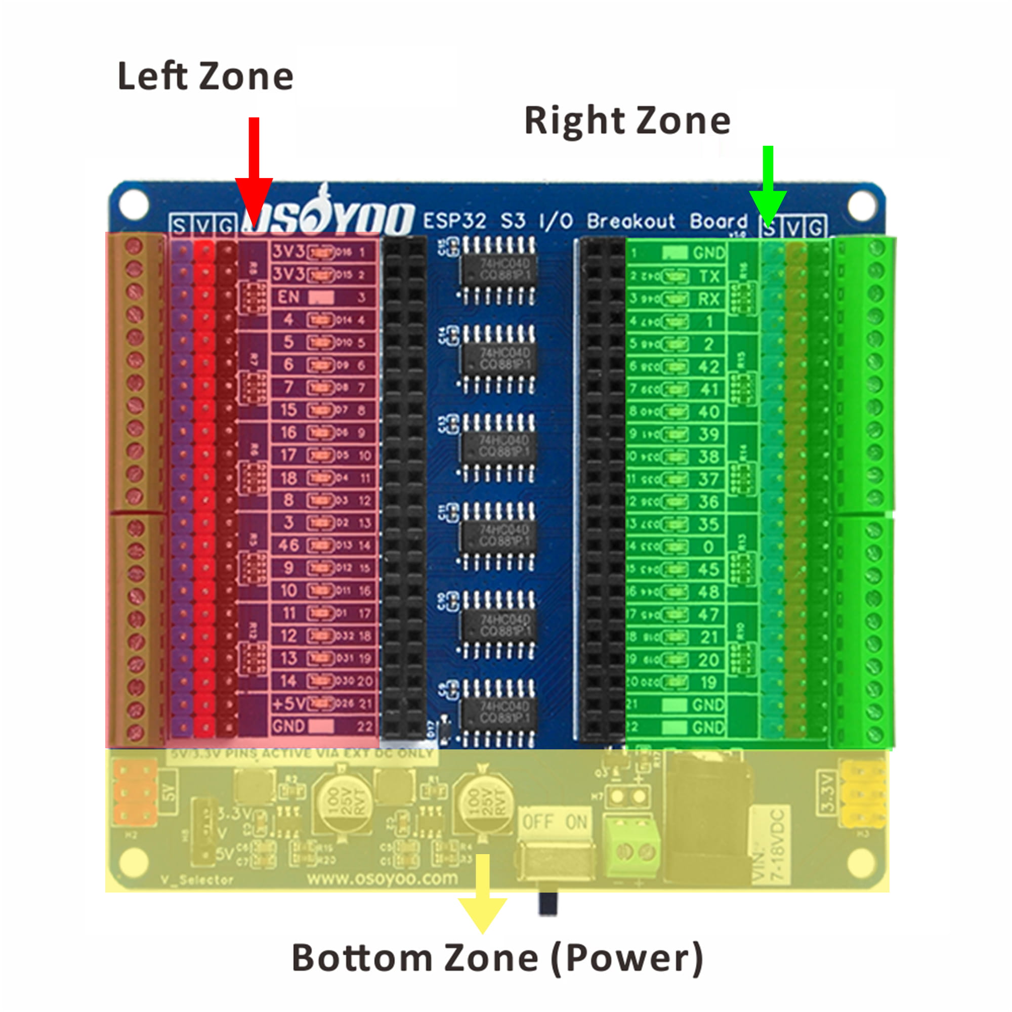
Fig 2 – PCB top view (component side)
The board is divided into three functional zones:
- Left Zone: Left-side MCU socket pins. Each GPIO row exposes an S (signal), V (V-rail), and G (GND) 3-pin header plus a screw terminal. A column of LED indicators sits alongside the socket.
- Right Zone: Right-side MCU socket pins — mirror arrangement of the left zone with identical S / V / G headers and screw terminals per row.
- Bottom Zone (Power Section): Two DC-DC converter modules, ON/OFF slide switch, DC barrel jack, VIN screw terminal, and V_Selector jumper.
5.2 Bottom View
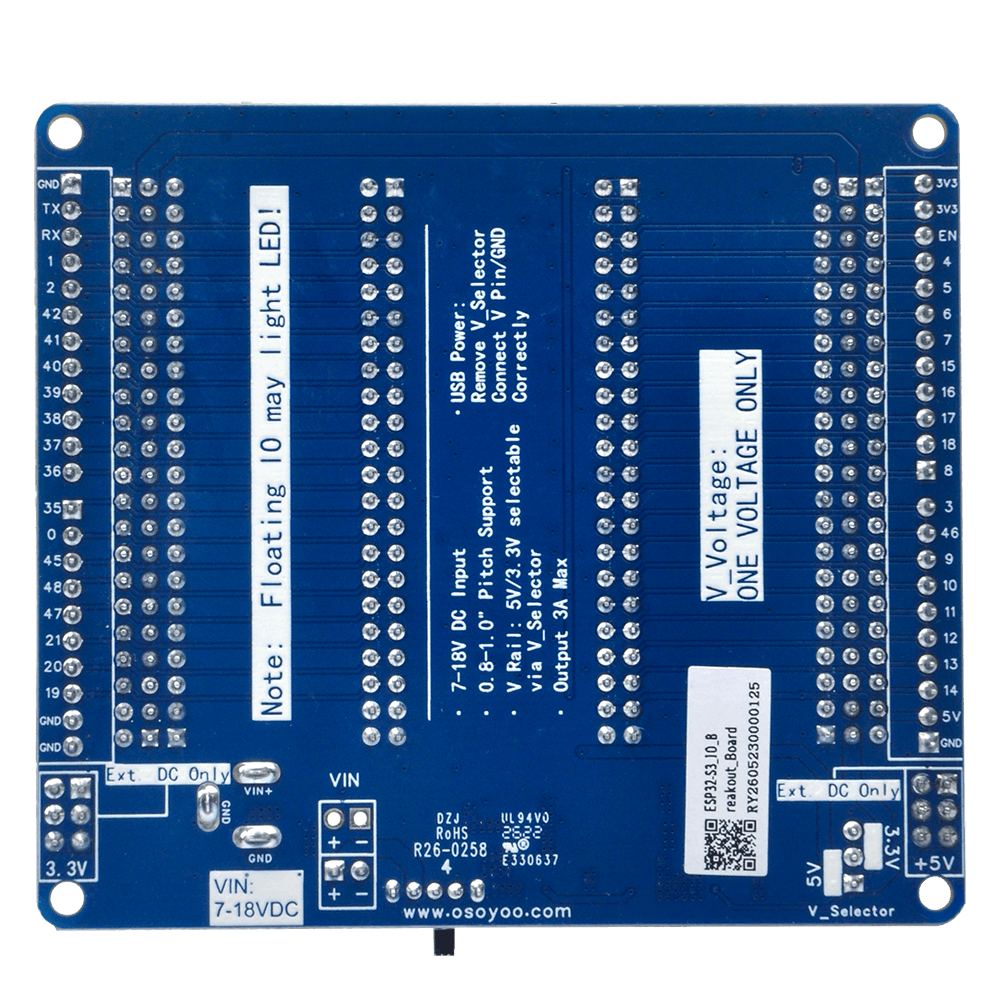
Fig 3 – PCB bottom view
5.3 Schematic Diagram
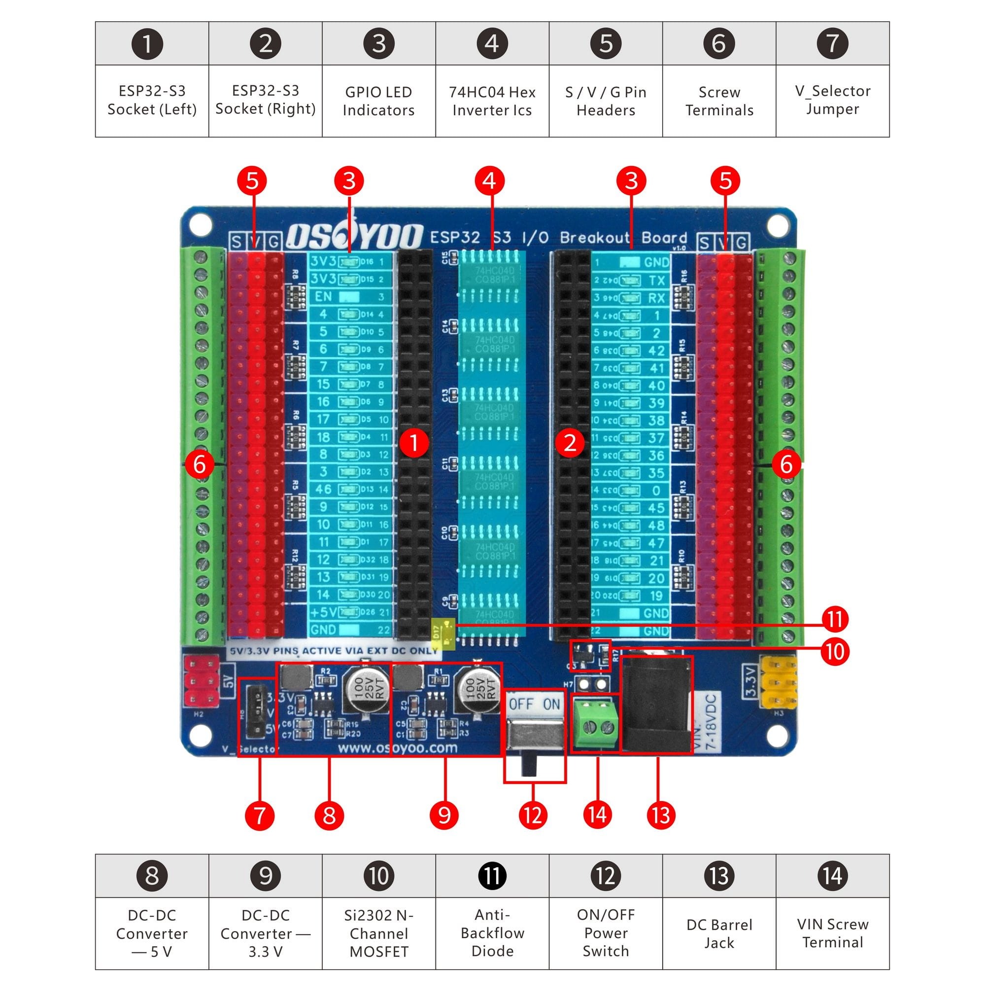
Fig 4 – Full schematic diagram
5.4 Component Descriptions
| No. |
Component |
Description |
| ① |
ESP32-S3 Socket (Left) |
22P female pin-header socket for the left pin row of the ESP32-S3 module. Accommodates 0.8 / 0.9 / 1.0 inch pin-row spacing. |
| ② |
ESP32-S3 Socket (Right) |
22P female pin-header socket for the right pin row. Same width accommodation as ①. |
| ③ |
GPIO LED Indicators |
One LED per accessible GPIO pin. Illuminates when the corresponding pin is HIGH; off when LOW. Driven by 74HC04 ICs — not the MCU GPIO directly. |
| ④ |
74HC04 Hex Inverter ICs |
Multiple 74HC04 ICs buffer and invert GPIO signals to drive the LED indicators. Output goes LOW when GPIO is HIGH, forward-biasing the LED. Zero GPIO load. |
| ⑤ |
S / V / G Pin Headers |
3-pin 2.54 mm headers per GPIO row: S = MCU signal, V = V-rail power (3.3 V or 5 V), G = GND. Connect sensors, servos, relay modules, etc. |
| ⑥ |
Screw Terminals |
Screw-clamp connectors alongside each S / V / G header row for solid, vibration-resistant wire connections. Ideal for thicker wires and field installations. |
| ⑦ |
V_Selector Jumper |
3-pin jumper selecting the V rail voltage: bridge center to the 3.3 V or 5 V pad. Default: 3.3 V. Remove entirely when operating on USB power only. |
| ⑧ |
DC-DC Converter — 5 V |
JW5357MSOTB#TR step-down converter. Converts 7–18 V DC input to regulated 5 V at up to 3 A. |
| ⑨ |
DC-DC Converter — 3.3 V |
JW5357MSOTB#TR step-down converter. Converts 7–18 V DC input to regulated 3.3 V at up to 3 A. |
| ⑩ |
SI2302 N-Channel MOSFET |
Reverse polarity protection circuit. Blocks all current if the DC power input polarity is accidentally reversed. |
| ⑪ |
Anti-Backflow Diode |
Isolation diode between the DC-DC 5 V output and the USB 5 V path. Prevents USB 5 V from flowing back into the DC-DC converter output when DC input is absent. |
| ⑫ |
ON/OFF Power Switch |
Slide switch controlling the DC-DC peripheral V rail output. Switching OFF cuts peripheral power without interrupting MCU USB power. |
| ⑬ |
DC Barrel Jack |
5.5×2.1 mm barrel jack, center positive. Input: 7–18 V DC from a wall adapter or lab bench supply. |
| ⑭ |
VIN Screw Terminal |
Alternative DC input (+ / −). Same 7–18 V range as the barrel jack. Use when connecting via loose wire leads or a battery pack. |
6. Compatible ESP32-S3 Boards
The breakout board is designed primarily for 22P-per-side (44-pin total) ESP32-S3 development boards. It is also compatible with boards that have fewer pins, provided the pin physical order matches the socket labelling. Always verify pin alignment before powering on.
| Board Model |
Pin Count |
Typical Width |
Compatibility |
| ESP32-S3-DevKitC-1 (N8 / N8R8 / N16R8) |
44 (22×2) |
0.9 inch |
✔ Recommended |
| ESP32-S3-DevKitM-1 |
38 (19×2) |
0.9 inch |
✔ Compatible (3 pins per side unused) |
| Other ESP32-S3 boards with matching 22P layout |
Up to 44 |
0.8–1.0 inch |
⚠ Verify pin order before use |
⚠ Important: The pin arrangement (which side is left / right, and the top-to-bottom order) must match the breakout board silkscreen. Inserting a board with a different pin order may short power rails to GPIO pins, permanently damaging both the ESP32-S3 module and the breakout board. When in doubt, verify pinout with a multimeter before powering on.
7. Power Configuration
7.1 External DC Power (7–18 V) — Recommended for Full Operation
1
Connect a 7–18 V DC supply to the barrel jack (center positive, 5.5×2.1 mm) or VIN screw terminal (+ / −). A 12 V / 2 A wall adapter is recommended for most projects.
2
Set the V_Selector jumper — bridge the center pin to the 3.3 V pad (default) or 5 V pad, depending on your peripheral requirements.
3
Slide the ON/OFF switch to ON.
4
Insert the ESP32-S3 board into the socket, aligning pin 1 to the marked orientation on the silkscreen. Connect peripherals to the S / V / G headers or screw terminals.
⚠ Always verify V_Selector voltage before connecting any peripheral. Applying 5 V to a 3.3 V-only sensor or module will permanently damage it.
7.2 USB Power Only — Firmware Upload / GPIO Indicator Mode
When only the MCU’s USB connection is present (e.g., laptop connection for programming), the DC-DC converters are inactive. The GPIO LED indicators can still be powered from the MCU’s USB-derived supply:
1
Remove the V_Selector jumper cap. This disconnects the V rail from the DC-DC outputs and eliminates any back-feed path through the 3.3 V converter.
2
Connect a wire from the ESP32-S3 board’s 3.3 V output pin to any V pin on the breakout board’s peripheral header rail. This supplies the 74HC04 indicator ICs from USB power.
3
Ensure GND is common. The socket GND pins share GND automatically when the MCU is seated in the socket.
Note: The on-board anti-backflow diode already protects the 5 V DC-DC converter output from USB back-feed. Removing the V_Selector jumper additionally protects the 3.3 V converter path and is recommended as a precaution. When the board is used solely for firmware development with no peripherals attached, this entire step may be skipped.
7.3 V_Selector Voltage Selection
| Jumper Position |
V Rail Voltage |
Typical Use Case |
Default |
| Center ↔ 3.3 V pad |
3.3 V |
3.3 V sensors, I²C / SPI modules, OLED displays |
✔ Default |
| Center ↔ 5 V pad |
5 V |
Standard RC servos, 5 V relay modules, WS2812B LED strips, HC-SR04 sonar |
— |
| Jumper removed |
No V rail output |
USB-only mode; indicator power supplied manually from MCU 3.3 V pin |
— |
⚠ Critical — One Voltage Only: All V pins share a single common rail. Never connect power sources of different voltages to different V pins simultaneously — this will create a dead short between the two voltage sources and may permanently damage the board and any connected peripherals.
8. Getting Started – Arduino Tutorial
8.1 Arduino IDE Setup for ESP32-S3
Step 1 — Install Arduino IDE 2.x
Download and install Arduino IDE 2.x (version 2.0 or later). Arduino IDE 1.x is also supported but 2.x is recommended.
Step 2 — Add the ESP32 Board Package URL
Open File → Preferences. In the Additional boards manager URLs field, paste the following URL:
https://raw.githubusercontent.com/espressif/arduino-esp32/gh-pages/package_esp32_index.json
Step 3 — Install the ESP32 Package
Go to Tools → Board → Boards Manager. Search for esp32 and install esp32 by Espressif Systems (version 2.0.14 or later).
Step 4 — Select Your Board and Settings
Go to Tools → Board → ESP32 Arduino and choose the entry matching your module. For the ESP32-S3-DevKitC-1, select ESP32S3 Dev Module.
| Setting |
Recommended Value |
Notes |
| Board |
ESP32S3 Dev Module |
Or your specific board name |
| USB CDC On Boot |
Enabled |
Enables Serial monitor over native USB port |
| Flash Size |
8 MB or 16 MB |
Match your module variant |
| Upload Speed |
921600 |
Reduce if upload fails |
| Port |
Select correct COM port |
Appears after connecting USB |
Tip — Entering Download Mode: If the board is not detected or upload fails, hold the BOOT button on the ESP32-S3 board, press and release RESET, then release BOOT. The board enters download mode and the COM port should appear. Click Upload in the IDE.
8.2 Example 1: LED Blink & GPIO Indicator Verification
This example demonstrates the breakout board’s core feature — watching the GPIO LED indicator respond to firmware in real time. No external wiring is needed beyond the USB cable.
Hardware Setup
- Seat the ESP32-S3-DevKitC-1 in the breakout board socket (align pin 1 carefully).
- Connect the USB cable from your PC to the ESP32-S3 board.
- No DC power adapter is needed for this example.
- To enable LED indicators: remove the V_Selector jumper and connect a wire from the ESP32-S3’s 3.3 V pin to any V header pin on the breakout board.
Expected Result
The LED indicator for GPIO 48 (or whichever pin you choose) blinks in sync with the digitalWrite calls. HIGH = LED ON; LOW = LED OFF.
/*
 * Example 1: LED Blink / GPIO Indicator Verification
 * Watch the breakout board LED indicator for the chosen pin toggle.
 * No external components required.
 */

const int TEST_PIN = 48;   // GPIO 48 — onboard RGB data pin on DevKitC-1
                           // Change to any GPIO you want to test

void setup() {
  delay(1000);             // Let strapping pins settle after boot
  pinMode(TEST_PIN, OUTPUT);
}

void loop() {
  digitalWrite(TEST_PIN, HIGH);   // Breakout board LED indicator: ON
  delay(500);
  digitalWrite(TEST_PIN, LOW);    // Breakout board LED indicator: OFF
  delay(500);
}
8.3 Example 2: GPIO Flowing Light
This example steps through all accessible GPIO pins sequentially, lighting each breakout board LED indicator one by one. It is the fastest way to verify every GPIO indicator is functioning and to learn the physical-to-logical pin mapping of your ESP32-S3 board.
Hardware Setup
- Seat the ESP32-S3-DevKitC-1 in the breakout board socket.
- Power via 12 V DC adapter (recommended) or USB. If USB only, follow the USB power steps in Section 7.2 to supply the indicator ICs.
- No external components needed — all LEDs are on the breakout board.
Expected Behavior
- LEDs light up one by one at 0.2 s intervals, sequencing through all GPIO pins.
- All LEDs remain on for 2 seconds.
- All LEDs turn off simultaneously and stay off for 2 seconds.
- Sequence repeats indefinitely.
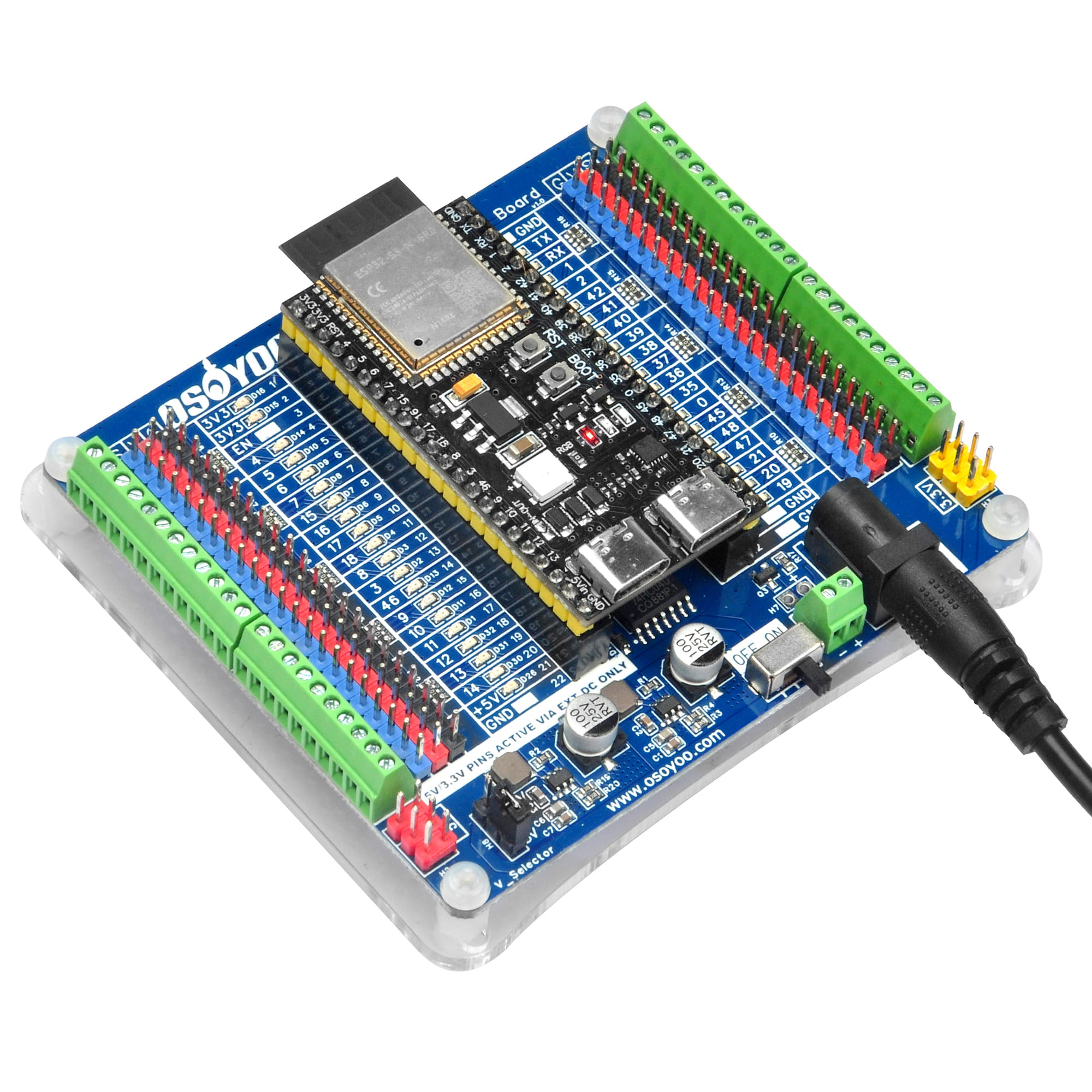
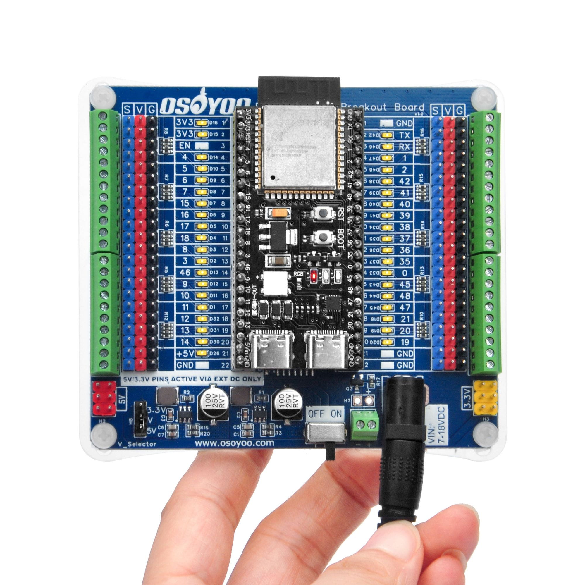
Fig 5 – Hardware connection example for the flowing light demo
/*
 * Example 2: GPIO Flowing Light — ESP32-S3 IO Breakout Board
 * Sequence: light up pins one by one → all on (2 s) → all off (2 s) → repeat
 *
 * Pin list based on ESP32-S3-DevKitC-1 physical layout.
 * Left header (J1) and Right header (J3) GPIO-capable pins.
 */

const int pins[] = {
  // Left header J1 (top to bottom, GPIO pins only)
  1, 2, 42, 41, 40, 39, 38, 37, 36, 35, 0, 45, 48, 47, 21,
  // Right header J3 (top to bottom, GPIO pins only)
  4, 5, 6, 7, 15, 16, 17, 18, 8, 3, 46, 9, 10, 11, 12, 13, 14
};

const int PIN_COUNT = sizeof(pins) / sizeof(pins[0]);

void setup() {
  // Wait 1 s for strapping pins (GPIO 0, 45, 46) to finish boot tasks
  delay(1000);

  for (int i = 0; i < PIN_COUNT; i++) {
    pinMode(pins[i], OUTPUT);
    digitalWrite(pins[i], LOW);   // Start with all LEDs off
  }
}

void loop() {
  // Phase 1: Light up one by one
  for (int i = 0; i < PIN_COUNT; i++) {
    digitalWrite(pins[i], HIGH);
    delay(200);
  }

  // Phase 2: All on — hold 2 s
  delay(2000);

  // Phase 3: All off simultaneously
  for (int i = 0; i < PIN_COUNT; i++) {
    digitalWrite(pins[i], LOW);
  }

  // Phase 4: All off — hold 2 s
  delay(2000);
}
Note on GPIO 0, 45, 46 (Strapping Pins): These pins control the ESP32-S3 boot mode. The delay(1000) at the start of setup() ensures they complete their boot-time function before being reconfigured as outputs. Do not remove this delay.
8.4 Example 3: Servo Motor Control
This example demonstrates connecting a standard RC servo to the breakout board using the S / V / G header. The servo uses the V rail for power, so set V_Selector to 5 V before connecting.
Hardware Setup
| Servo Wire Color |
Connect To |
Notes |
| Orange / White (Signal) |
S pin on the GPIO 7 row |
PWM signal from ESP32-S3 GPIO 7 |
| Red (VCC) |
V pin (any row) |
V_Selector must be set to 5 V |
| Brown / Black (GND) |
G pin (any row) |
Common ground |
- Set V_Selector jumper to 5 V.
- Connect a 12 V DC adapter and switch the power switch ON.
- Plug the servo into the GPIO 7 S / V / G header as above.
- Upload the sketch below and open Serial Monitor at 115200 baud.
/*
 * Example 3: Servo Motor Control via S/V/G Header
 * Library required: "ESP32Servo" by Kevin Harrington
 *   Install via Arduino IDE: Tools -> Manage Libraries -> search "ESP32Servo"
 *
 * Wiring: servo signal -> GPIO 7 S header, servo VCC -> V (5V), servo GND -> G
 */

#include

Servo myServo;
const int SERVO_PIN = 7;

void setup() {
  Serial.begin(115200);
  delay(1000);
  myServo.attach(SERVO_PIN, 500, 2400);  // Min/max pulse width in microseconds
  Serial.println("Servo initialized.");
}

void loop() {
  Serial.println("Moving to 0 deg");
  myServo.write(0);
  delay(1000);

  Serial.println("Moving to 90 deg");
  myServo.write(90);
  delay(1000);

  Serial.println("Moving to 180 deg");
  myServo.write(180);
  delay(1000);
}
⚠ Reminder: Standard servos require 5 V. Ensure V_Selector is bridged to the 5 V pad before connecting the servo, and that the DC power adapter is connected — servos draw more current than USB can provide.
9. Important Notes
- Verify Pin Alignment Before Powering On: The physical pin order of your ESP32-S3 board must match the breakout board’s socket silkscreen. Inserting a board with a different pin arrangement can short VCC directly to GPIO pins. When using a non-recommended board, verify with a multimeter before applying power.
- Floating GPIO Pins — LED Flicker: A GPIO in floating / high-impedance state (input mode without pullup or pulldown) may cause its LED indicator to glow dimly or flicker. Always define a pin mode in your sketch using
pinMode() with OUTPUT, INPUT_PULLUP, or INPUT_PULLDOWN.
- ESP32-S3 Strapping Pins (GPIO 0, 45, 46): These pins influence boot mode during reset. Always include a startup
delay(1000) in setup() before driving these pins as outputs.
- V Rail is Fully Interconnected: All V-rail pins on the board share a single common bus. Do not connect power sources of different voltages to different V pins — this creates a short circuit.
- Confirm V_Selector Voltage Before Connecting Peripherals: Applying 5 V to a 3.3 V-only device will permanently damage it. Check the jumper position every time before adding new hardware.
- Maximum DC Input Voltage: Do not exceed 18 V on the VIN input. Higher voltages can damage the DC-DC converters and other board components.
- Minimum DC Input Voltage: A minimum of 7 V is required for the DC-DC converters to regulate correctly. Input below 7 V will result in unstable or insufficient output voltage.
- Per-Rail Current Limit: Each DC-DC converter is rated at 3 A maximum. Ensure the total current draw of all peripherals connected to a given rail does not exceed this limit.
- USB-Only Mode: When operating from USB power alone, remove the V_Selector jumper to prevent any back-feed into the DC-DC converters. The built-in diode already protects the 5 V path; removing the jumper additionally protects the 3.3 V path.
- LED Indicator Behavior Summary:
| GPIO State |
LED Indicator |
| Output HIGH |
LED ON (solid) |
| Output LOW |
LED OFF |
| Floating / High-Z (no pullup/down) |
May glow dimly or flicker |
| Input with internal pull-up |
LED ON |
| Input with internal pull-down |
LED OFF |
10. Mechanical Information
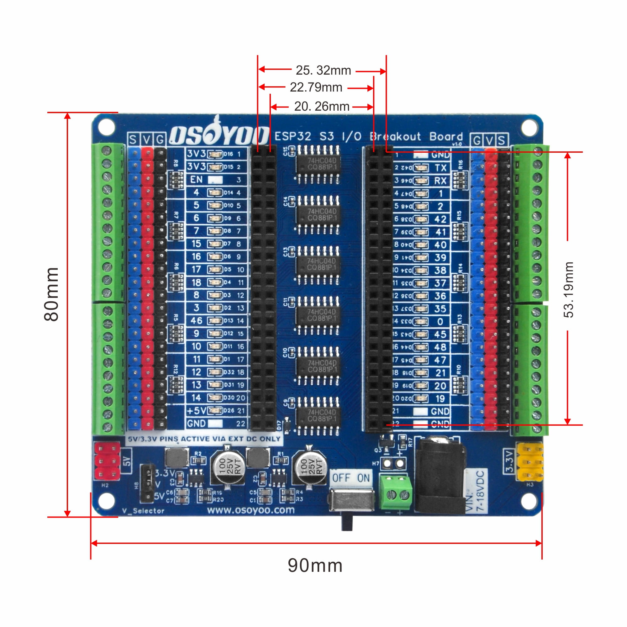
Fig 6 – PCB outline (see production drawing for exact dimensions)
| Parameter |
Value |
| PCB Dimensions |
See production drawing (2D_PCB顶面.png) |
| Mounting Holes |
4 × M3 (one at each corner) |
| Mounting Hole Diameter |
3.2 mm |
| PCB Thickness |
1.6 mm |
| PCB Color / Finish |
Blue, ENIG |
Note: Exact dimensions and mounting hole positions are shown in the production drawing. Values above are reference only and may change between PCB revisions.
11. Related Documents
| Document |
File / Link |
| Schematic Diagram |
SCH_原理图.png |
| PCB Top 2D Drawing |
2D_PCB顶面.png |
| PCB Bottom 2D Drawing |
2D_PCB底面.png |
| Wiring Connection Photo |
实物 连接图.jpg |
| Arduino Example Sketch |
参考示例代码gpio–led-esp32_s3.ino |
| 74HC04 Datasheet |
Hex inverter IC — Texas Instruments / Nexperia |
| SI2302 Datasheet |
N-Channel MOSFET — reverse polarity protection |
| JW5357MSOTB#TR Datasheet |
DC-DC step-down converter IC |
| ESP32-S3 Datasheet |
Espressif Systems – ESP32-S3 Datasheet (PDF) |
| ESP32-S3-DevKitC-1 User Guide |
Espressif Documentation Portal |
| Arduino IDE Download |
www.arduino.cc/en/software |
OSOYOO Related Products
MCU Debug Shield Series
38P ESP32 Breakout Board
30P ESP32/ESP8266 Breakout
Arduino Nano Breakout Board