


I.Objective
II.Parts and Devices
III.Hardware Installation
IV.Circuit Connection
V.Software Installation
VI.How to play

| Buy from US |
Buy from UK |
Buy from DE |
Buy from IT |
Buy from FR |
Buy from ES |
Buy from JP |
 |
 |
 |
 |
 |
 |
 |

In this project we will connect Robot Car to WIFI and Use an APP to control the car through Internet. This is a typical Internet of Things(IoT) Application.

OSOYOO Mecanum Wheels Robotic Car Chassis x 1 (2x left-wheels/2x right-wheels and 4x motor)
OSOYOO Mega2560 board fully compatible with Arduino
OSOYOO V1.0 WIFI Shield x 1
OSOYOO Model X motor driver x 2
OSOYOO Battery box x 1
18650 Batteries(3.7V) x 2

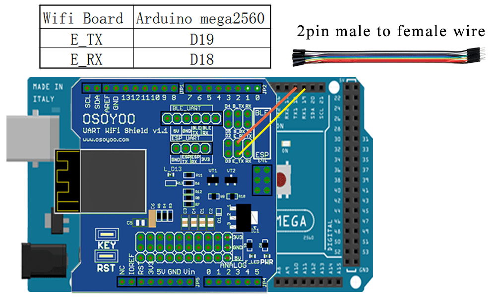
If you just finishes all Lesson 1 – Lesson3 please keep all lesson connections same as it is. Then plug out bluetooth from WIFI Shield.

Remove the connection B_TX and B_RX to D18 and D19.
Connect E_TX to D19(RX1) and E_RX to D18(TX1)
(Note: You need split 2 pcs of male-to-female jumper wires from our 10-pc jumper wire bundle. Any color from the bundle will be ok. The rest of 8 pcs wires are as spare parts for potential broken or damaged wires.)

STEP 1: Install latest Arduino IDE (If you have Arduino IDE version after 1.1.16, please skip this step). Download Arduino IDE from https://www.arduino.cc/en/Main/Software?setlang=en , then install the software.
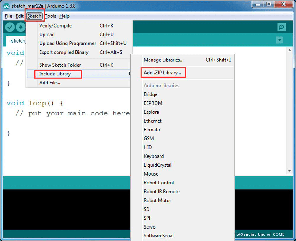
STEP2: Please download the library zip file from WiFiEsp-master .Open Arduino IDE ->click Sketch ->Include Library ->Add .ZIP library , then load above zip file into Arduino.
STEP3: Search Google Play or Apple Store with the Keywords “OSOYOO WIFI UDP Robot Car Controller ” and Download the APP.
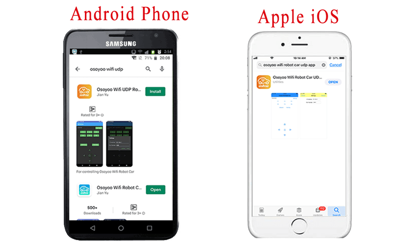
You can also directly download APP from https://osoyoo.com/driver/arduino-udp/udp-robot.apk
STEP4: Arduino Sketch code Installation:
Download: https://osoyoo.com/driver/arduino-udp/mecanum-2560-lesson5UDP.zip
Unzip the downloaded file , enter the mecanum-2560-lesson5UDP folder, you will see two sub-folder :
mecanum-2560-lesson5C and mecanum-2560-lesson5D
These two folders have program for two WIFI modes:AP mode and STA mode. The Arduino sketches for these two modes are different. Let’s explain these two modes one by one

When working in AP mode, our robot car itself will become a WIFI Hot Spot. Our cell phone can connect to Robot Car as its wifi client. The IP address of Robot is fixed as 192.168.4.1 and It is not connected to WAN.
(1)Open mecanum-2560-lesson5D, upload the code into Arduino

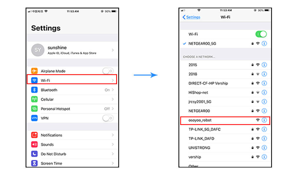
(2) Open your Arduino Serial monitor and set 9600 baud,then you will see a similar result as AP mode. A new WIFI SSID “osoyoo_robot” with IP address 192.168.4.1 will show up in the window. This means your Robot car has a WIFI Hot Spot name “osoyoo_robot” , its IP address is 192.168.4.1, port No.8888
(3)Now your Robot car become a WIFI Hot Spot and set IP address as “192.168.4.1” to your APP Setting section. Port number keep default value 8888
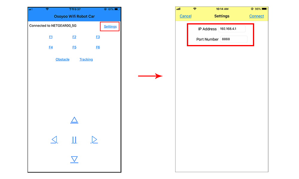
(4) Connect your cell phone to “osoyoo_robot” wifi hot_spot,you can use Mobile phone control the robot car.
(5)You can click the ◄ ► ▲ ▼ direction keys to make the car move. Use “||” pause key to stop the car movement.
Click Obstacle to shift left side, Click Tracking to shift right side.
Click F1 to make upper-left diagonal movement, Click F3 to make upper-right diagonal movement
Click F4 to make back-left diagonal movement, Click F6 to make back-right diagonal movement.

In STA mode, robot car does not work as a wifi hotspot. Instead, it will become an internet node in your LAN. You need tell Arduino sketch what is your local router’s WIFI SSID and password, then Arduino talks to router and get its own LAN IP address from DHCP server. You can use Mobile APP to access the robot car’s IP address and control its movement.
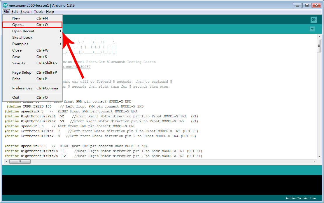
(1) Please open mecanum-2560-lesson5C folder . mecanum-2560-lesson5C.ino code into Arduino
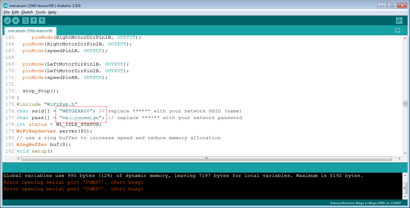
(2) You need change the code Line 176 and Line 177 :
char ssid[] = “YOUR_ROUTER_SSID”; // replace this with your router wifi SSID
char pass[] = “YOUR_ROUTER_WIFI_PASSWORD”; // replace with your wifi password
(3) Upload the sketch to Arduino. Finally, click the Serial monitor window in upper right corner of Arduino IDE and set 9600 baud,then you will see following result:
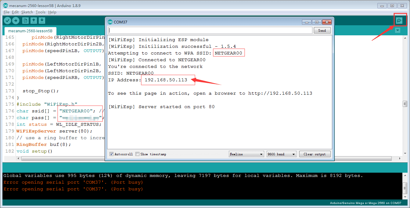
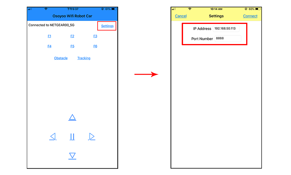
(4)In this mode, your will see an IP address which is our LAN IP address assigned by my router. Please write down this IP address and click Setting to set up robot IP address and set this IP address to your APP Setting section (no need change default port 8888 in APP).
(5)Now your Robot car is connected to your LAN, you can use Mobile phone under same LAN to control the robot car. If your APP is in WAN, you need to go to your Router Control Panel, forward Port 8888 to Robot car LAN IP address, then you can use Router IP to control the car. This feature makes our robot car A REAL INTERNET OF THING device
(6)You can click the “< ” “>” ” ^” ” v ” direction keys to make the car move. Use “||” pause key to stop the car movement.
Click Obstacle to shift left side, Click Tracking to shift right side.
Click F1 to make upper-left diagonal movement, Click F3 to make upper-right diagonal movement
Click F4 to make back-left diagonal movement, Click F6 to make back-right diagonal movement
FAQ about the WIFI UDP APP and sketch Code:
Q1)How to adjust SPEED of the car
A: If you want change the speed performance of the robot car, please following parameters in line 11 to 13:
#define SPEED 85
#define TURN_SPEED 90
#define SHIFT_SPEED 130
SPEED value determines forward moving speed
TURN_SPEED value determines turning speed
SHIFT_SPEED value determines parallel shifting speed
Q 2)What happened when you press buttons in OSOYOO WiFi UDP Robot Car APP ?
A: When you press a button of the APP, APP will send a single-letter message through UDP protocol to target device (in this example, our Arduino Wifi Shield)
| Button |
UDP message |
| F1 |
F |
| F2 |
G |
| F3 |
H |
| F4 |
I |
| F5 |
J |
| F6 |
K |
| ▲ |
A |
| ▼ |
B |
| ► |
R |
| ◄ |
L |
| square |
E |
| OBSTACLE |
O |
| TRACKING |
T |
Q3)How does Arduino handle the UDP command?
Line 230 to line 245 in mecanum-2560-lesson5C.ino file are the codes which react to Cell phone command. For example, when ▲ is pressed, according to Q1 table, a letter “A” command was sent from Cell phone to Arduino. Line 233 case ‘A’ …. statement will make the car make car moving forward.
      char c=packetBuffer[0];
      switch (c)    //serial control instructions
      {
        case 'A':go_advance(SPEED);;break;
        case 'L':left_turn(TURN_SPEED);break;
        case 'R':right_turn(TURN_SPEED);break;
        case 'B':go_back(SPEED);break;
        case 'E':stop_Stop();break;
        case 'F':left_shift(0,150,0,150);break; //left ahead
        case 'H':right_shift(180,0,150,0);break; //right ahead
        case 'I':left_shift(150,0,150,0); break;//left back
        case 'K':right_shift(0,130,0,130); break;//right back
        case 'O':left_shift(200,150,150,200); break;//left shift
        case 'T':right_shift(200,200,200,200); break;//left shift
        default:break;
      }