Overview
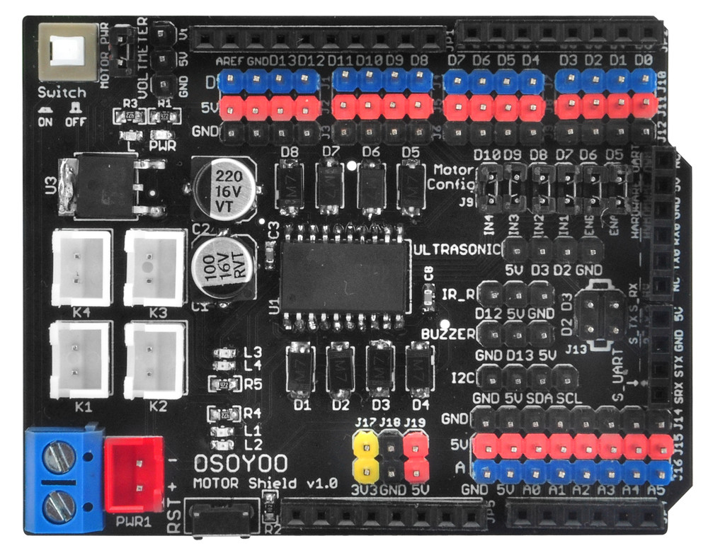
The OSOYOO Motor Shield is based on the L293DD (datasheet), which is a monolithic integrated high voltage,high current four channel driver designed to accept standard DTL or TTL logic levels and drive inductive loads (such as relays solenoides, DC and stepping motors) and switching power transistors.To prevent board damages, all driver lines are diode protected from back EMF. The maximum supply voltage supported by this board is 20V
It uses a L293DD chip which deliveries output current up to 1.2A each channel. it requires a 6V to 15V power supply to power the motor and also includes an on-board 5V voltage regulator for powering the driver chip. It lets you drive two DC motors with your Arduino board, controlling the speed and direction of each one independently.
You can use UNO R3 microcontroller and add external components to complete a variety of amazing experiments, such as smart robot DIY. When DIY your robot, it is necessary to use the motor driver board to drive the DC motors, however, sometimes need to connect the motor drive board to UNO using lots of jumper wires, pretty inconvenient.
The Motor shield can be powered directly from Arduino or from external power source. It is strongly encouraged to use external power supply to power the motor shield.
This board also provides direction LED indicators for both channels and this is very usefull during setup stage to verify the firmware behaviour; the led indicators work also without appling a real motor to the output.
Features
- Standard pin out for UNO Shield
- Based on L293DD motor driver chip
- Drive 2 DC Motor or 1 Stepper
- External power input available
- External power switch
- RST button
- 5V/3.3V/GND power interfaces
- Motor driver power switch jumper
- Hardware uart interface/Software uart interface
- Sensors interfaces
- All gpio pin out
- Motor related convenient wiring via jumpers
- 4 direction indicator lights
- Heat sink for better performance
- Wifi IoT add-on function when working with OSOYOO WIFI module (https://osoyoo.com/2020/12/20/osoyoo-esp8266-wi-fi-module/)
- Bluetooth function when working with HC-02 Bluetooth module (https://osoyoo.store/products/hc02-bluetooth-module-for-osoyoo-robot-car?variant=22561056948342)
CAUTION:
The Driver IC and Heat sink may become very hot when working with current more than 1000mA.
Specifications
- Logical part of the input voltage VD: 5V
- Input Voltage (recommended):7 ~ 12V
- Input Voltage (limit): 6-20V
- Logical part of the work current Iss: <36mA
- Drive part of the operating current Io: 1.2A
- Maximum power dissipation: 25W (T = 75 Celsius)
- Control signal input level: High 2.3V low -0.3V
- Working temperature: -25 + 130 Celsius
- Screw power socket: 5.0mm pitch terminal
- belt clip and can be controlled via front row access signal
- Drive Type: Dual power H-bridge driver
- Pin occupancy: D7 ~ D10 direct drive motor
- Supports PWM / PLL mode motor speed cont
- Weight 29 g
- Dimensions 68.5 x 53 mm
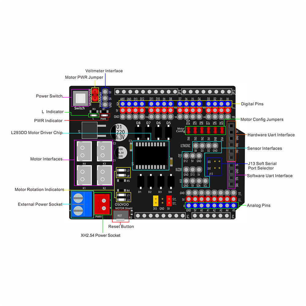
Hardware Overview
-
- Power Switch:Control the external input power, press the switch to turn on the power, press again to turn off the power
- Motor PWR Jumper: Connect the jumper cap, the motor drive chip works normally, remove the jumper cap and stop working
- VOLTMETER Interface: Three-wire digital voltmeter interface, display external power supply voltage
- Digital pin out: Lead out digital signal interfaces
- L indicator: Connect with Arduino pin D13
- PWR indicator:
- Motor Config Jumpers: When the jumper is connected, the motor chip control pin is connected to the corresponding Arduino io port by default. If necessary, you can also take off the jumper cap and connect other Arduino io ports via Dupont cable to control the motor.
- Motor IN1-Arduino D7
- Motor IN2-Arduino D8
- Motor IN3-Arduino D9
- Motor IN4-Arduino D10
- Motor ENA-Arduino D5
- Motor ENB-Arduino D6
- Motor Interface:K1 and K2(K3 and K4) can connect Motor A(B) for DC Motor.
- L293DD Motor Driver Chip
- Motor rotation indicators
- External Power Socket(Blue power socket/XH2.54 power socket): External Power supply for Motor Shield, range 6-15V.
- Reset button: pressed to reset the shield and Arduino
- Auino analog pin out
- Sensor interfaces: In order to facilitate wiring, we designed corresponding interfaces for commonly used sensors and connected them to the signal pins of Arduino
- Hardware Uart Interface: Connect the Arduino D1 to TX0, connect the Arduino D0 to RX0.
- Software Uart Interface: Connect to those pins that allow serial communication on Arduino.
- J13 Soft Serial Port Selector: J13 provides a convenient way to set the soft serial port. You can use a jumper to set the D2 and D3 ports as soft serial ports. If you need to use other pins, you can remove the jumper cap and use jumper wires to connect S_TX/S_RX to those pins that allow serial communication on Arduino.
- Fritzing Part File Download: https://osoyoo.com/picture/V2.0_Model_3_Robot/Motor-shield-V1.0.fzz.zip


Hello!
I want to use Arduino attachInterrupt() to pins D2 and D3 (to perform pulse counting). Are these used by the UltraSonic sensor?
D3 does not seem to rise above 2.5V and I am trying to understand why.
Many thanks,
– jon
FWIW: This was my coding error. Pin3 was set to output using pinMode(Trig_PIN, OUTPUT); I need to move the echo sensor to other, unused, pins.
Hi,
I am trying to use the soft UART serial ports SRX and STX on the motor project for two-port receive. What should I define the two pins as(using SoftwareSerial Library)?
Also, if I were to use the J13 serial ports and the SRX/TX ports at the same time, would the arduino communicate with both ports at the same time? If so, what should I write in my code to declare them as?
Hi there!
I want to know how can I, using block programming, reverse the motors direction but as one of them is connected to Digital Pin 8 and another to Pin 10 (K2 & K3 or K1 and K2) I have no mean to do it through the normal HIGH/LOW values (full speed vs. stop, but no reverse).
Thanks!
in order to use mBlock programming, you need connect
IN1 —D12 //Left motor direction
IN2 —D11 //Left motor direction
IN3 —D9 //Right motor direction
IN4 —D10 //Right motor direction
ENA —D5 // Needs to be a PWM pin to be able to control motor speed ENA
ENB —D6 // Needs to be a PWM pin to be able to control motor speed ENB
You can use Forward Block to make car move forward and Backward to make car make reverse roate.
For more information, please read following project:
https://osoyoo.com/2021/08/22/arduino-graphic-programming-learning-kit-lesson-14-basic-car/