Overview In this project, we learn how to use SPI protocol to exchange complex data between Raspberry Pi and external device. SPI is a simple communication protocol to send data which can save a lot of GPIO pin resources. We will only how to program SPI in this lesson, you can google protocol detail if you are interested.
This external device is MCP3008 analog-digit-convert(ADC) chip. As we’ve learned from previous lessons, the Raspberry Pi could do many projects with various digital sensors. Unlike Arduino Board, Raspberry Pi doesn’t have integrated ADC(analog to digital converters) so it cannot read analog inputs.
In this lesson, we will use MCP3008 ADC chip to convert analog signal to digital signal and send it to Raspberry Pi through SPI.
Hardware Preparation
1 * Raspberry Pi
1 * Breadboard
1 * MCP3008
Several jumper wires
Software Preparation Note: In this lesson, we remotely control raspberry pi via PuTTy on PC. To learn how to config raspberry pi, please visit lesson 1: getting started with raspberry pi.
Work Principle
The MCP3008 is a 10-bit 8 channels Analog-to-Digital Converter (ADC) with SPI(Serial Peripheral Interface Bus) interface. learn more about SPI, please click here . You can also use MCP3004 instead which has 4 input channels , for the datasheet about MCP3004/MCP3008, please visit: https://osoyoo.com/driver/MCP3008_datasheet.pdf
In this project, we use Raspberry Pi 3.3V and GND as MCP3008 Input Channel 1 and Input Channel 2 respectly. the MCP3008 will convert the analog signal to digital quantity, this enables the Raspberry Pi to interpret analog voltages that are in turn typically emitted by analog-based sensors to reflect a measure of a physical characteristic such as acceleration, light intensity or temperature.
Hardware Setup
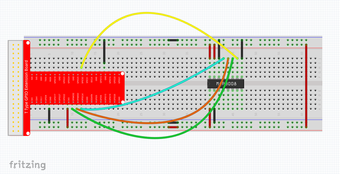
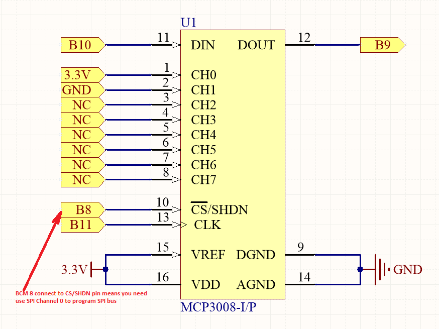
MCP3008 uses SPI interface, wiring up the MCP3008 to Pi as following connection graph, NC means Not Connected. B# means BCM system. i.e B10 means BCM GPIO 10 ( Physical 19, wPi#12).
*DIN/DOUT PINS
MCP3008 communicates with Raspberry Pi through SPI protocol . In raspberry Pi, SPI BUS pin pair are BCM 10(out) and BCM 9(in) which are connected to MCP3008 DIN pin and DOUT pin. We call it a BUS because BCM 10/BCM 9 can be shared with multiple devices.
Pi accept maximum two devices for SPI bus. We call them spiChannel 0 and spiChannel 1. Raspberry Pi use BCM 7 and BCM 8 pin to control these two channels. When an external Device enable pin is connected with Pi BCM 8 pin, it is a spiChannel 0. When device. enable pin is connected with Pi BCM 7 pin, it is a spiChannel 1 device. From above graph, our MCP3008 is a spiChannel 0 device because CS/SHDN(enable pin) is connected with B8. **Analog Input Pin CH0,CH1…CH7 MCP3008 can read 8 different analog input signal from pin CH0,CH1..CH7. The Chip will compare input voltage with Maximum allowed voltage and output an integer between 0 to 1023. Input analog max value are defined by VREF pin. In this sample circuit, CH0 connected to 3.3V which is same as VREF voltage, so output integer for CH0 is 1023. Ch1 connected to GND, its output is 0. Output will be sent through SPI serial protocol.
Sample code
we’ll provide two kinds of codes for C language users and Python language users. For C Language users, please take following steps:
Note: please be sure installation wiringpi. Click here, you can learn more about how to check whether installing wiringpi and install wiringpi
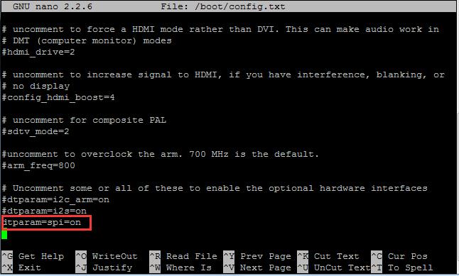
Step 1)Enalble SPI, open file /boot/config.txt , find the code line as followed, change it as dtparam=spi=on
sudo nano /boot/config.txt
Press “ctrl” + “X” and then type “Y” to save the file which you revised.
Step 2) reboot the raspberry pi by typing following command:
sudo reboot
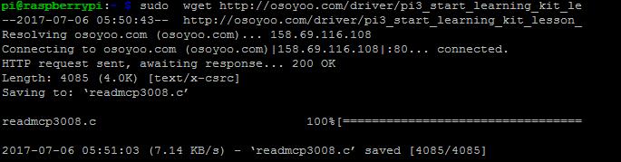
Step 3) Download the sample code from osoyoo by typing following commands:
Note: If you want to customize the sample code file , you can use nano editor to edit source code by typing following command in terminal:
sudo nano readmcp3008.c
Step 4) Compile Code
C language is high level language. Before running the project, the code need to compile as an executable file. Please enter the following command: gcc -Wall -o readmcp3008 readmcp3008.c -lwiringPi Note: gcc: is GNU Compiler Collection. If you want to write your own C code and compile to run it, you need to master gcc. for more information about gcc, please visit here -Wall: to get more error when compile the code -o: to name the compiled file. You can name the file as your like. here we name as readmcp3008 buzzer.c: means the original file which is compiled -lwiringPi: is to load the library wiringPi (l is short for library)
Step 5) Run the Program
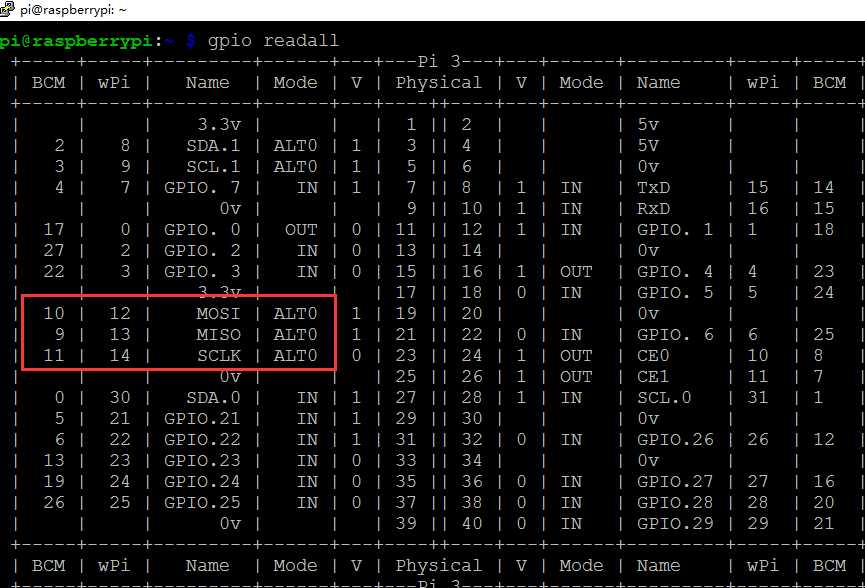
a)Before running the program, using command: gpio readall to check if the MOSI、MISO、SCLK(B10、B9、B11) work mode is ALT0 (alternative functions), if not, please set them to ALT0 by typing terminal command as following:
gpio -g mode 9 alt0
gpio -g mode 10 alt0
gpio -g mode 11 alt0
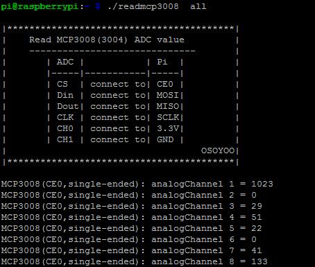
b) Read all value from ADC MCP3008 by typing the following command:
./readmcp3008 all
Once run the program, the terminal will show print message as code firstly, then show all channels value.
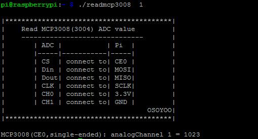
c) Read Channel 1 value from ADC MCP3008 by typing the following command:
./readmcp3008 1
Once run the program, the terminal will show print message as code firstly, then show the channel 1 value . because we connected the CH1 to 3.3v, CH2 to 0V, so the output channel l value is 1023, the output channel 2 is 0
Read the comments in following code and understand the programming principle
When programming with Python language , normally we use GPIO library called RPi.GPIO which comes with Rasbian Jessie OS. Click here, you can learn more about RPI.GPIO and Python.
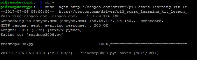
1) download sample code by typing following command in terminal:
Note: If you want to customize the sample code file , you can use nano editor to edit source code by typing following command in terminal:
sudo nano readmcp3008.py
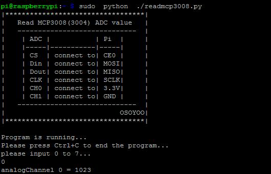
2) Run the program
sudo python ./readmcp3008.py
3) Running result
a)Then type the output Channel that you want to read, for example: if we type 0 (zero) in terminal and press enter, then the terminal will print the Channel 0 value.
b) if the input value is not in scope, it will print the prompt message.
Read the comments in following code and understand the programming principle
import time
import os
import RPi.GPIO as GPIO

# change these as desired - they're the pins connected from the
# define SPI port on the ADC to the Cobbler

# use BCM 11 as SPI clock signal
SPICLK = 11
#MISO and MOSI are the data pins required by SPI, google it for detail
#use BCM 9 as MISO to accept signal from external SPI output
SPIMISO = 9

#use BCM 10 as MOSI to to send signal to external SPI input
SPIMOSI = 10

#use BCM 8 as SPI CS to enable/disable extern SPI device
SPICS = 8

#DEBUG = 1

#setup function for some setup---custom function
def setup():
    GPIO.setwarnings(False)
    #set the gpio modes to BCM numbering
    GPIO.setmode(GPIO.BCM)
    # set up the SPI interface pins
    GPIO.setup(SPIMOSI, GPIO.OUT)
    GPIO.setup(SPIMISO, GPIO.IN)
    GPIO.setup(SPICLK, GPIO.OUT)
    GPIO.setup(SPICS, GPIO.OUT)

#print message at the begining ---custom function
def print_message():

    print ('|**********************************|')
    print ('|   Read MCP3008(3004) ADC value   |')
    print ('|   -----------------------------  |')
    print ('|    | ADC |           | Pi  |     |')
    print ('|    |-----|-----------|-----|     |')
    print ('|    | CS  | connect to| CE0 |     |')
    print ('|    | Din | connect to| MOSI|     |')
    print ('|    | Dout| connect to| MISO|     |')
    print ('|    | CLK | connect to| SCLK|     |')
    print ('|    | CH0 | connect to| 3.3V|     |')
    print ('|    | CH1 | connect to| GND |     |')
    print ('|   -----------------------------  |')
    print ('|                            OSOYOO|')
    print ('|**********************************|\n')
    print ('Program is running...')
    print ('Please press Ctrl+C to end the program...')
    print ('please input 0 to 7...')

# read SPI data from MCP3008 chip, 8 possible adc's (0 thru 7)
def readadc(adcnum, clockpin, mosipin, misopin, cspin):
        if ((adcnum > 7) or (adcnum < 0)):
                return -1
        GPIO.output(cspin, True)

        GPIO.output(clockpin, False)  # start clock low
        GPIO.output(cspin, False)     # bring CS low to enable MCP3008

        commandout = adcnum
        commandout |= 0x18  # start bit + single-ended bit
        commandout <<= 3    # we only need to send 5 bits here

        #Tell MCP3008 I am getting data from which ADC#
        for i in range(5):
                if (commandout & 0x80):
                        GPIO.output(mosipin, True)
                else:
                        GPIO.output(mosipin, False)
                commandout <<= 1
                GPIO.output(clockpin, True)
                GPIO.output(clockpin, False)
        #Read SPI data from MCP3008 and save it to variable adcout
        adcout = 0
        # read in one empty bit, one null bit and 10 ADC bits
        for i in range(12):
                GPIO.output(clockpin, True)
                GPIO.output(clockpin, False)
                adcout <<= 1 if (GPIO.input(misopin)): adcout |= 0x1 GPIO.output(cspin, True) adcout >>= 1       # first bit is 'null' so drop it
        return adcout

#main function
def main():
    #print info
    print_message()
    analogChannel = int(input())
    if (analogChannel < 0) or (analogChannel > 7):
        print ('input error analogChannel number!')
        print ('please input 0 to 7...')
    else:
        adc = readadc(analogChannel, SPICLK, SPIMOSI, SPIMISO, SPICS)
        print ('analogChannel %d = %d'%(analogChannel,adc))

#define a destroy function for clean up everything after the script finished
def destroy():
    #release resource
    GPIO.cleanup()
#
# if run this script directly ,do:
if __name__ == '__main__':
    setup()
    try:
            main()
    #when 'Ctrl+C' is pressed,child program destroy() will be executed.
    except KeyboardInterrupt:
        destroy()


 *DIN/DOUT PINS