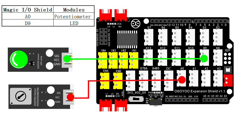
In this lesson, we will use a potentiometer module to control the light brightness of LED module . Both modules are connected to Osoyoo Magic I/O board for Arduino.
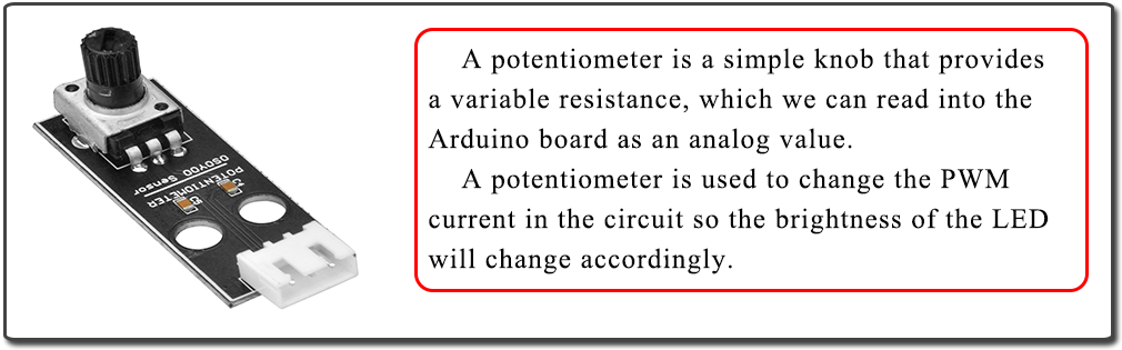
In this lesson, a potentiometer, or pot, is used to change the PWM current in the circuit so the brightness of the LED will change accordingly. And since the pot is an analog device, the current change is smooth, thus the blink brightness will gradually get bigger or smaller instead of going through an obvious stepwise process.
So what’s the difference between an analog value and a digital one? Simply put, digital means on/off, high/low voltage with just two states, i.e. either 0 or 1. But the data state of analog signals is a continuous range, for example, from 1 to 1023; Analog signals include those of light intensity, humidity, temperature, and so on.
What we mean by PWM here is the digitalization of analog signals, which is a process of approaching analog signals. Since the potentiometer inputs analog signals, it should be connected to analog ports, i.e. A0-A5, instead of digital ports.
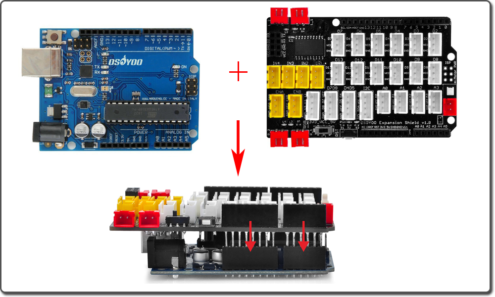
OSOYOO Basic Board for Arduino (Fully compatible with Arduino UNO rev.3) x 1
OSOYOO Magic I/O Shield for Arduino x1
OSOYOO Potentiometer Module(10k) x 1
OSOYOO LED Module x 1
OSOYOO 3-Pin PNP Cable x 2
USB Cable x 1
PC x 1
Notice: Shut off your battery or Unplug your power adapter when upload sketch code to OSOYOO Basic Board for Arduino.
You can download the code directly, then click “Open” in Mixly to choose the code you download:
Connect the OSOYOO Basic Board for Arduino to your computer using the USB cable. The green power LED (labelled PWR) should go on.
In this example, let’s see how to use potentiometer to change the luminance of an LED and receive the data of the potentiometer in Serial Monitor to see its value change.
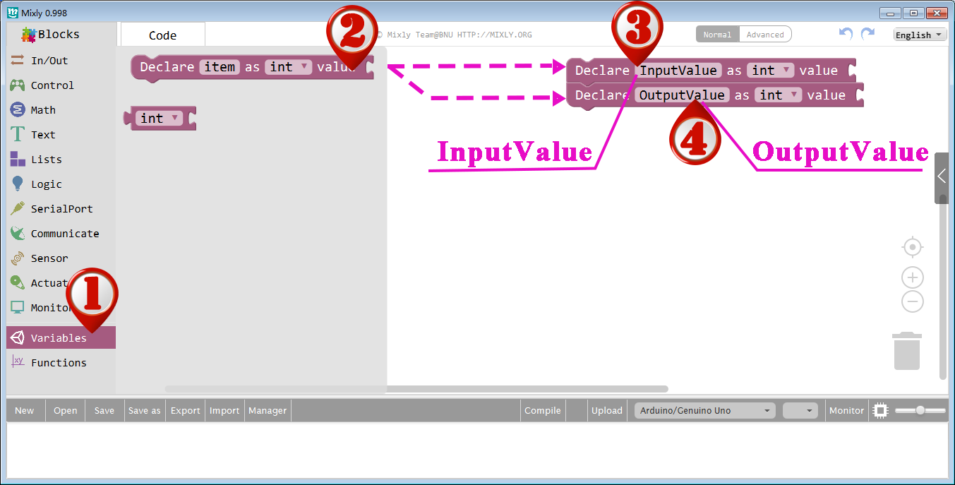
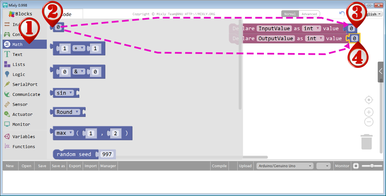
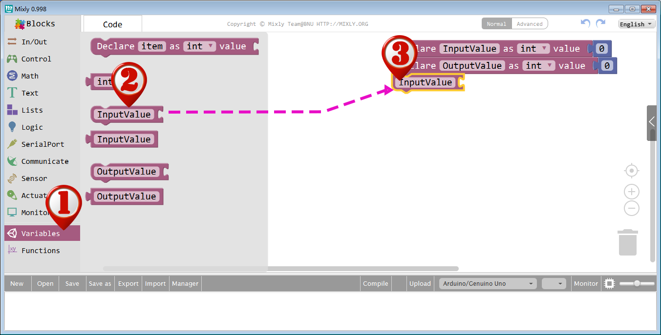
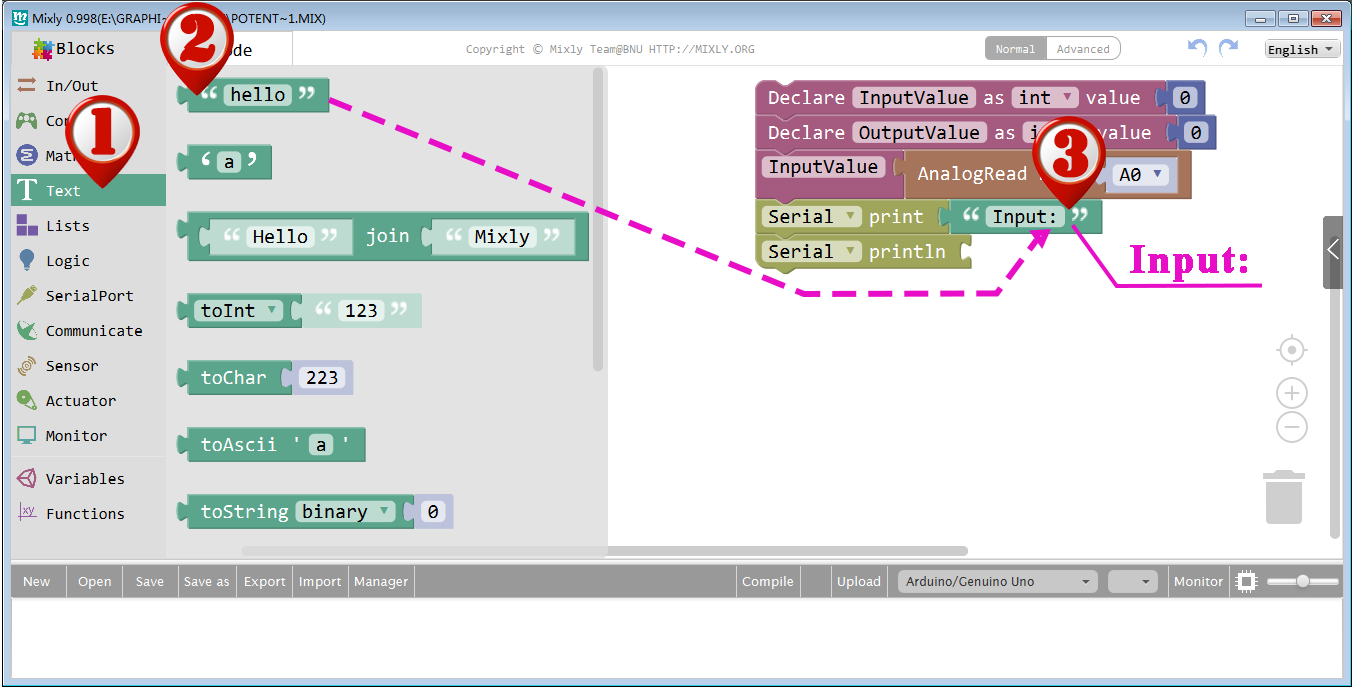
Declare two integer variables: Inputvalue, Output Value.
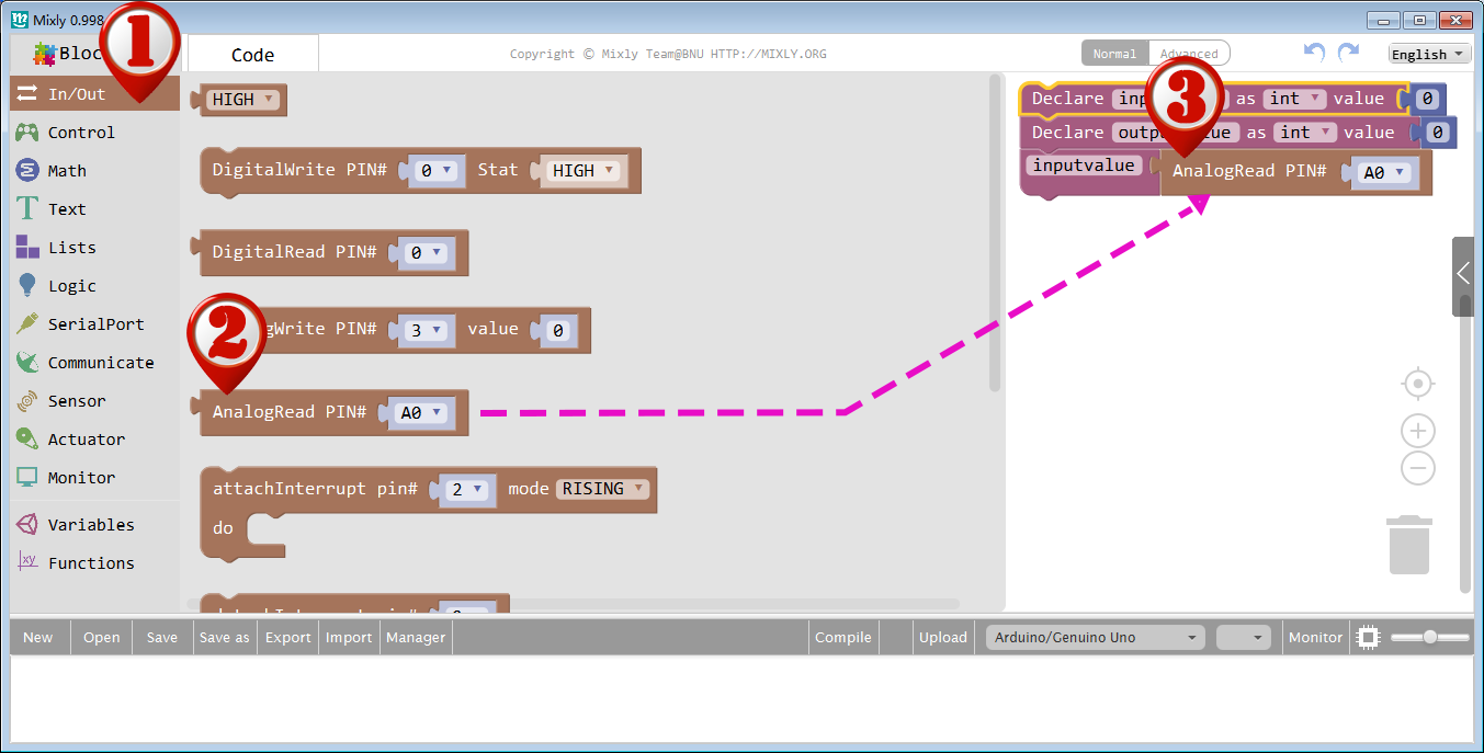
The potentiometer’s value is sent by the analog pin A0 to variable InputValue.
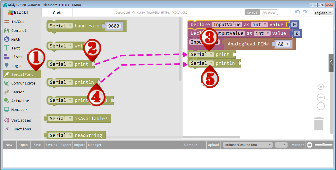
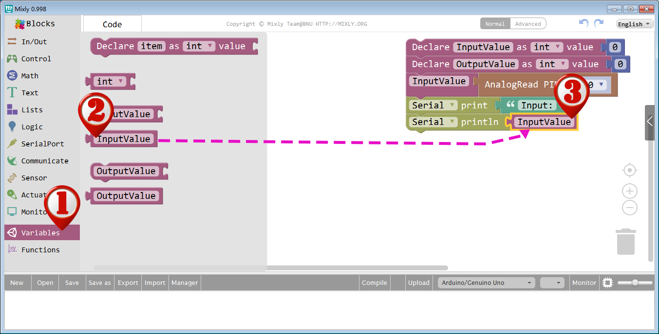
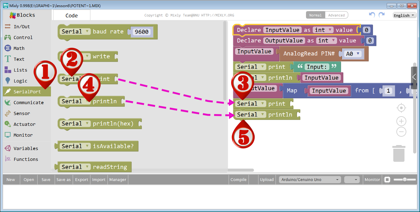
Set the following blocks to print ”Input:” and the InputValue, then jump to the next line automatically.
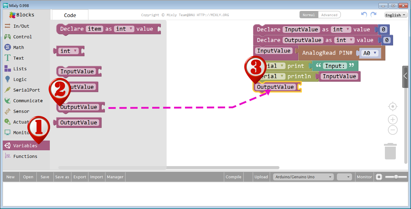
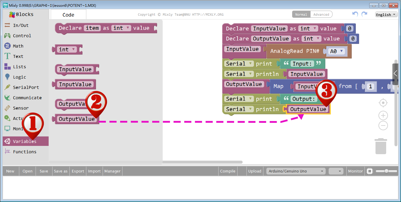
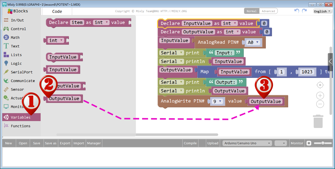
Click Variables category again, drag an OutputValue block to blank area as following picture:
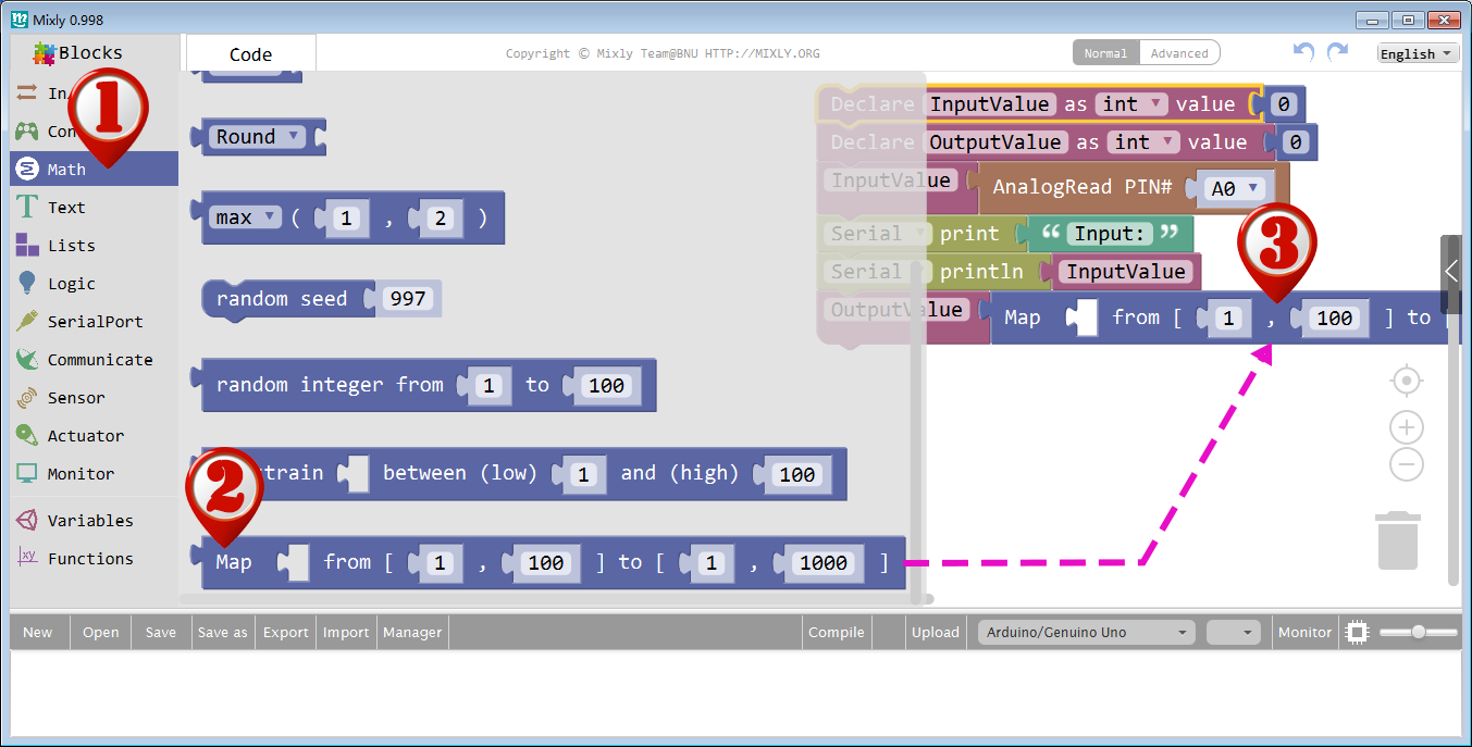
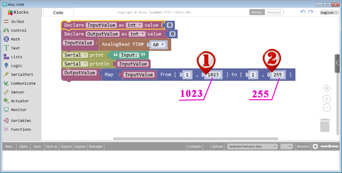
Click Math category, find the Map block in Math category:
Convert the value from 0-1023 proportionally to that in the range 0-255, and assign it to OutputValue.
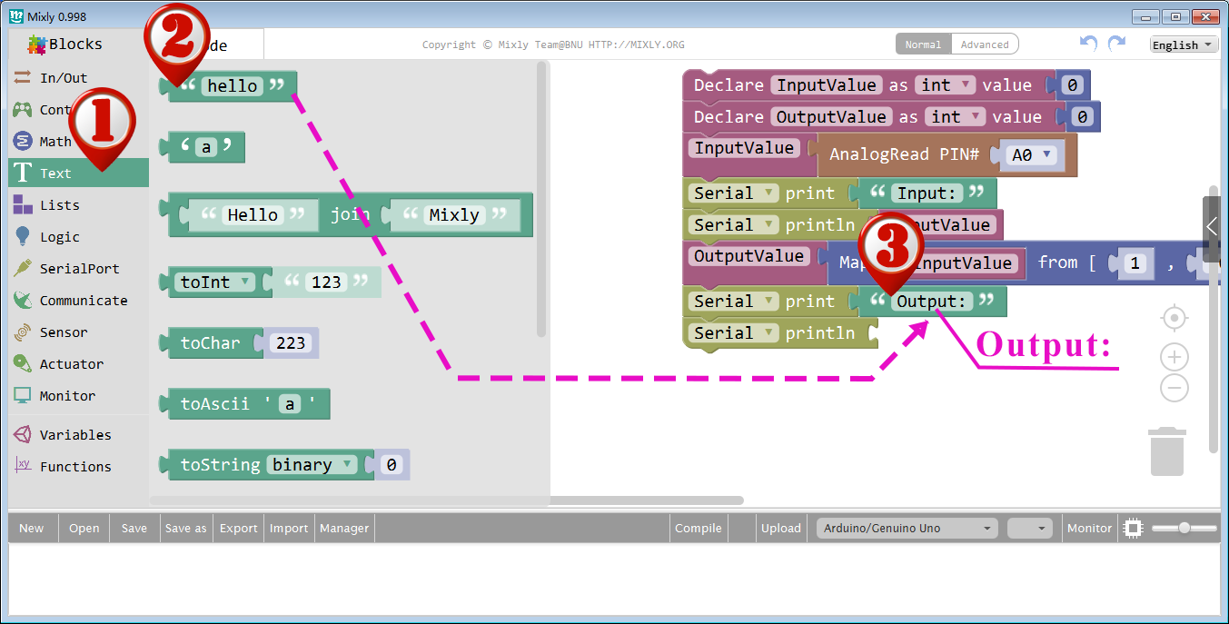
Set the following blocks to print”Output”and the OutputValue similarly.
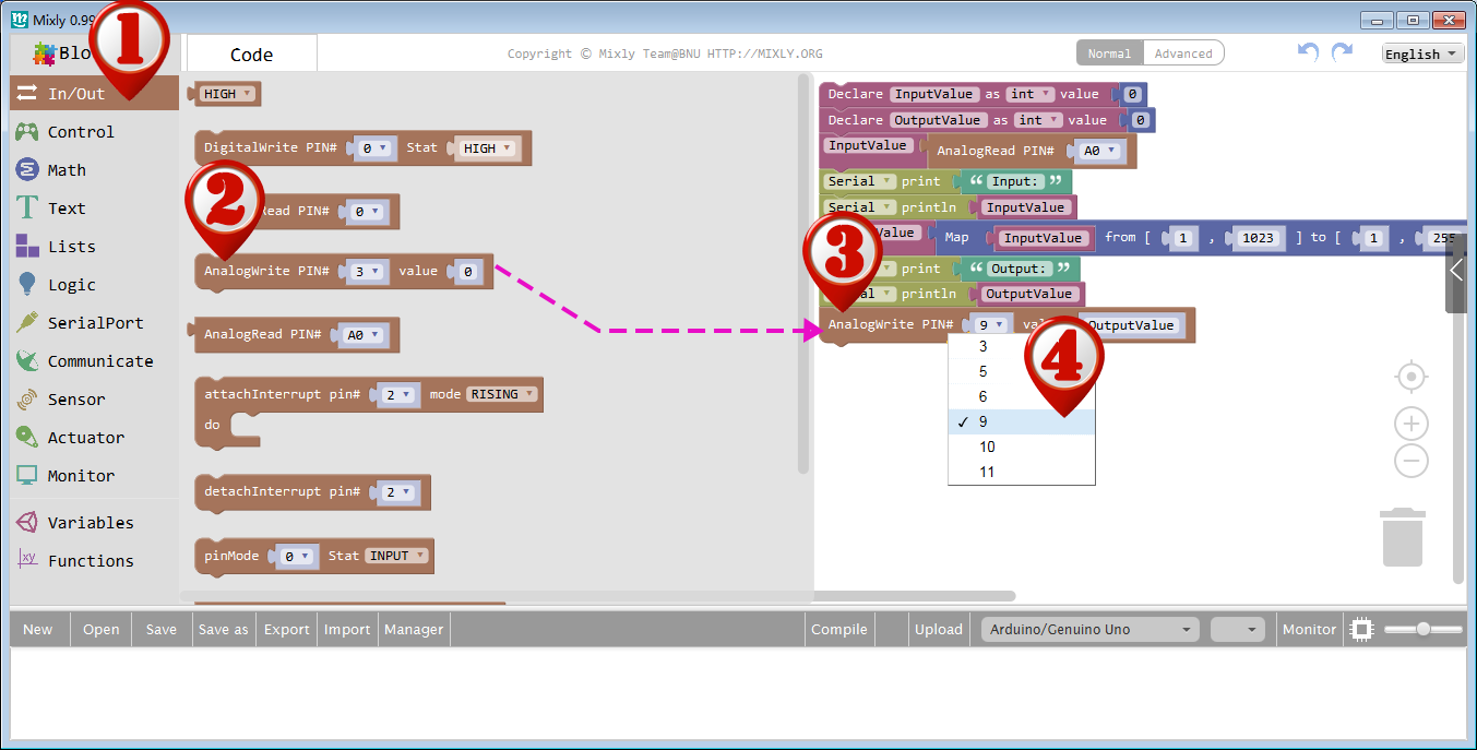
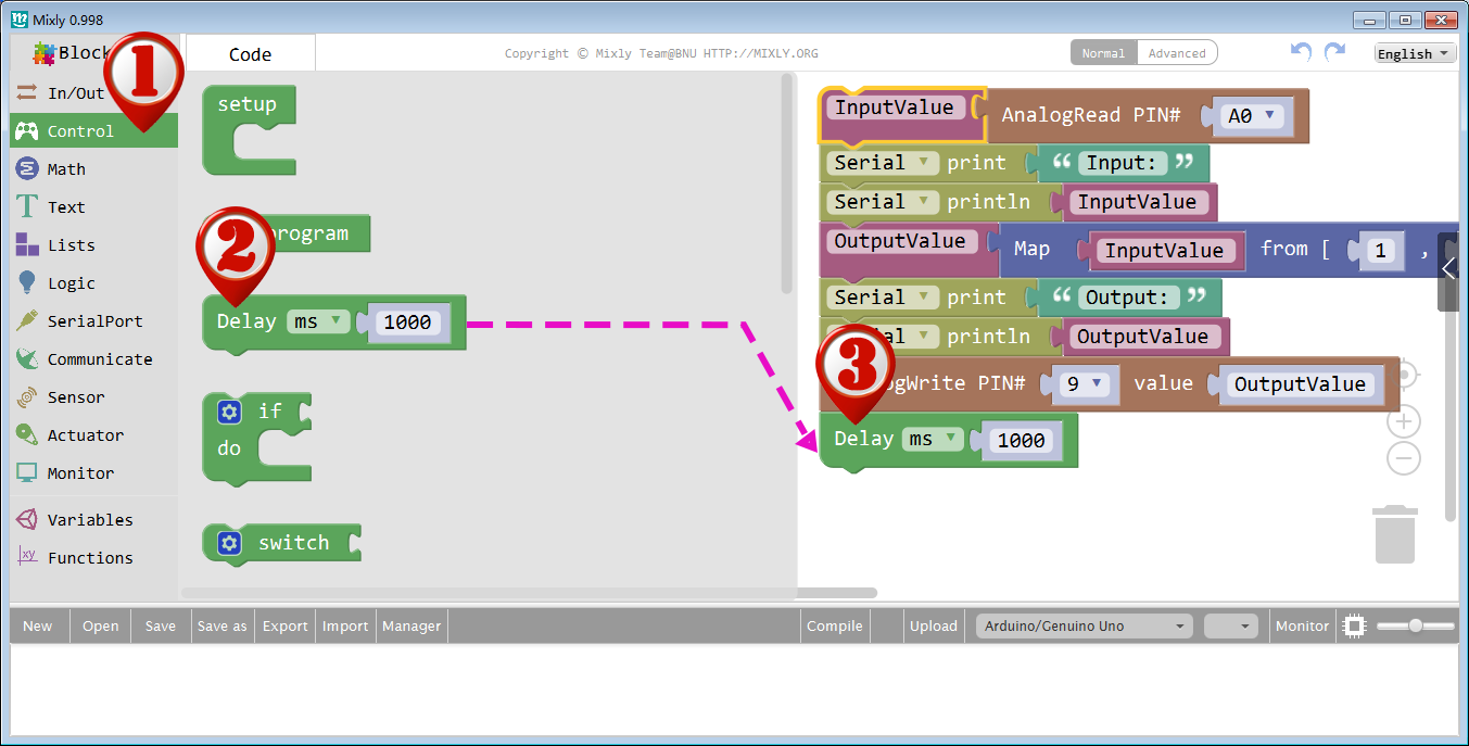
Drag another AnalogWrite block from In/Out section, Set pin 9 as output, and add a Delay for 1 second.
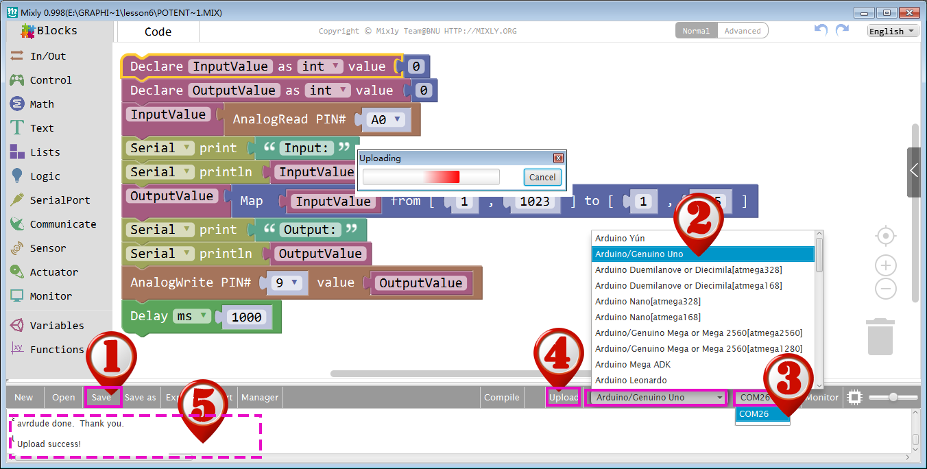
Click Save after programming is done. Select the board type and serial port before uploading. For instause a Uno board, just select Arduino/Genuino Uno.
Next,upload the code. If the uploading fails, check and correct the code according to the prompts.Finally, the status will change to ‘Upload success!’.
As you see, the potentiometer is connected to pin A0 of the Osoyoo Uno board, which can measure voltages from 0V to 5V. The corresponding returned value is from 0 to 1024. The measurement accuracy for voltage change is relatively high.
A few seconds after the upload finishes,rotate the shaft of the potentiometer and you should see the luminance of the LED change.
If you want to check the corresponding value changes, open the Serial Monitor and the data in the window will change with your spinning of the potentiometer knob.