


| Buy from US |
Buy from UK |
Buy from DE |
Buy from IT |
Buy from FR |
Buy from ES |
Buy from JP |
 |
 |
 |
 |
 |
 |
 |

In this lesson, we will show how to gradually change the luminance of an LED Module through mBlock graphic programming. Since the pulsing light looks like breathing, we give it a magical name – breathing LED. We’ll accomplish this effect with pulse width modulation (PWM).

- A laptop or Desktop PC which runs Windows or Mac computer
- OSOYOO Magic I/O Shield for Arduino x1
- Red LED Module x 1
- OSOYOO 3-Pin PnP cable x 1
- USB Cable x 1

What is PWM?
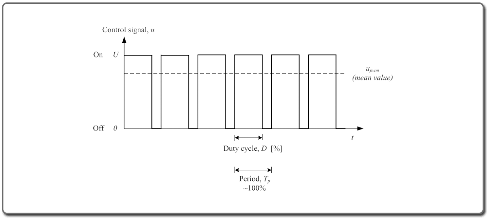
Pulse Width Modulation, or PWM, is a technique for getting analog results with digital means. In simple, PWM pin can generate “analog-like” current output controlled by computer program. Following words are detailed introduction about PWM, if you are not interested in such tech detail, you can skip them and directly go to HOW TO MAKE section.
Digital control is used to create a square wave, a signal switched between on and off. This on-off pattern can simulate voltages in between full on (5 Volts) and off (0 Volts) by changing the portion of the time the signal spends on versus the time that the signal spends off. The duration of “on time” is called the pulse width. To get varying analog values, you change, or modulate, that pulse width.
To get varying analog values, you change, or modulate, that pulse width. If you repeat this on-off pattern fast enough with an LED for example, the result is as if the signal is a steady voltage between 0 and 5V controlling the brightness of the LED. (See the PWM description on the official website of Arduino).
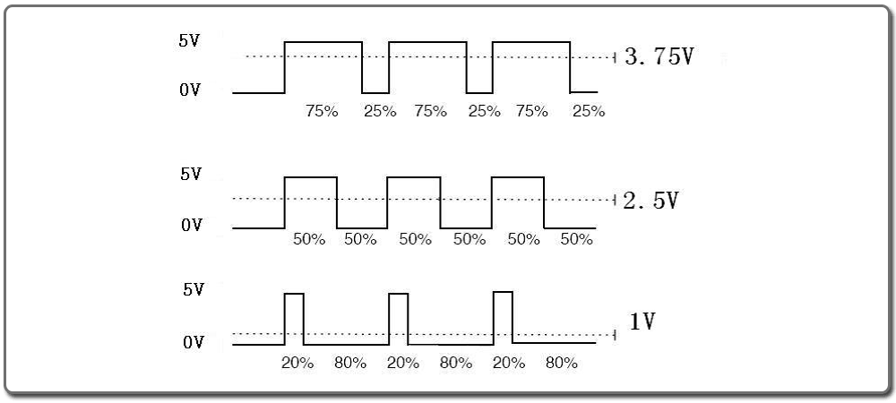
We can see from the top oscillogram that the amplitude of the DC voltage output is 5V. However, the actual voltage output is only 3.75V through PWM because the high level only takes up 75% of the total voltage within a period.
Here is an introduction to the three basic parameters of PWM:
- Duty cycle describes the proportion of “on” time to the regular interval or period of time.
- Period describes the reciprocal of pulses in one second.
- The voltage amplitude here is 0V–5V.

Firstly, please plug Osoyoo Magic I/O shield into UNO board as following:

Secondly, connect LED module to D3 port as following:
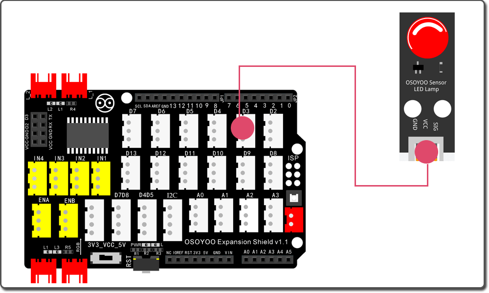
Finally, use the USB cable to connect your PC to the OSOYOO UNO board

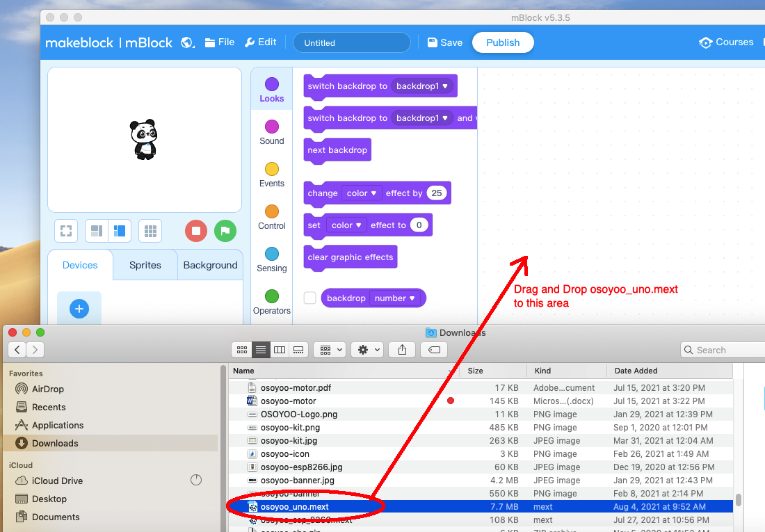
Step 1) If you haven’t install mBlock software in your PC, please read Lesson 1, download and install the software.
Step 2) Run the mBlock PC software by double click the lovely Panda icon. Drag and Drop osoyoo_uno_mext file(downloaded in Step 1) to mBlock software as following:
Now you will see a new device firmware in mBlock, see following picture:
Now mBlock software and OSOYOO_UNO device firmware have been successfully installed in our PC!
Now we will show you how to use blocks to turn above idea into reality.
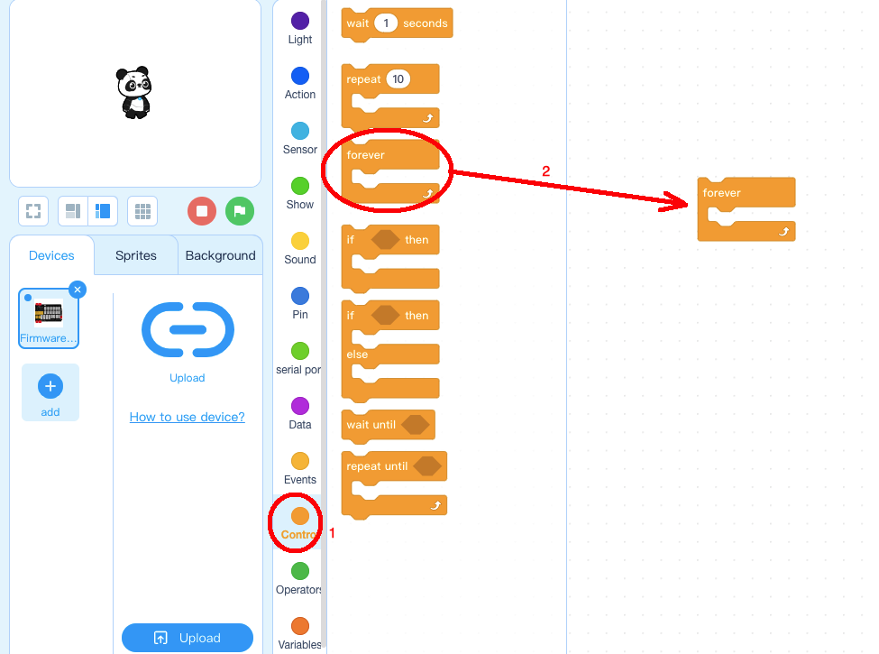
Step 1: Click Control, then Drag and drop Forever block to programming area as following:
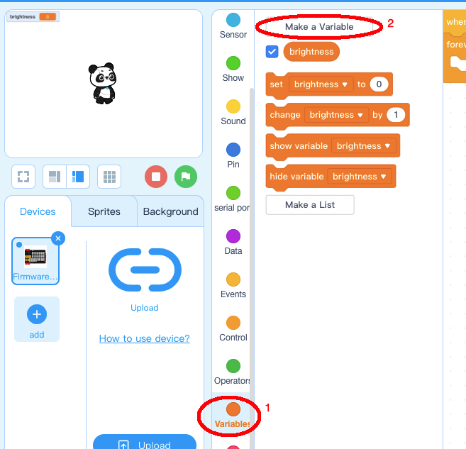
Step 2: Click Variable, make a variable and give it a name brightness:
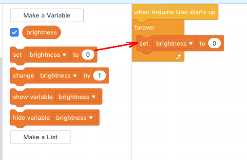
Step 3: drag a set brightness to 0 block to forever loop:
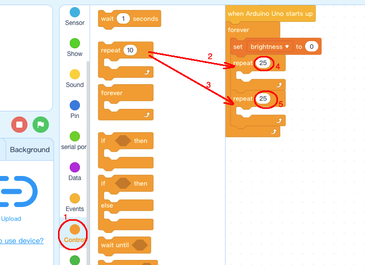
Step 4: Click Control category, add two repeat block, set repeat time to 25
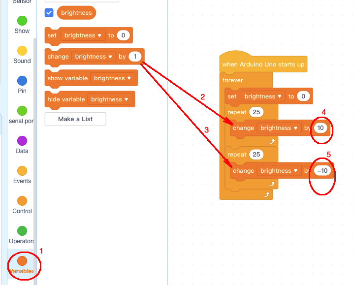
Step 5: Click Light, Add 2 pcs change brightness blocks inside repeat 25 blocks:
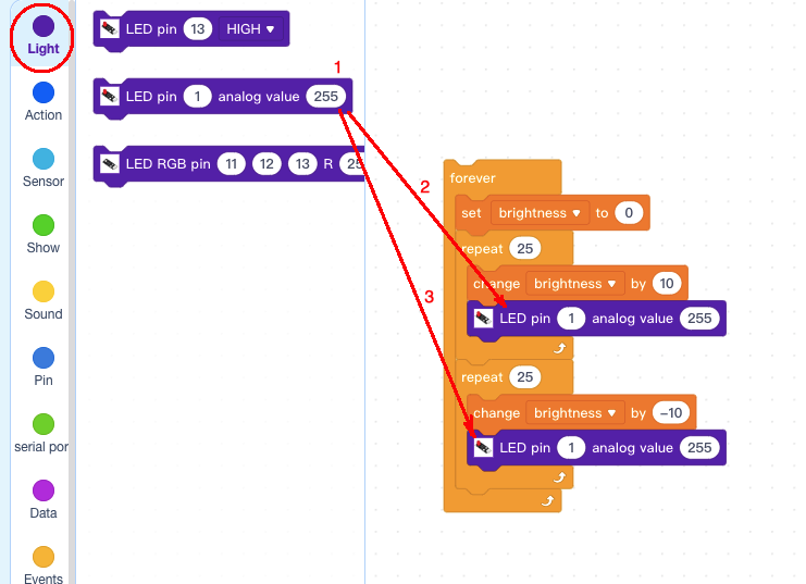
Step 6: Click Light, Add 2 pcs LED pin analog value blocks below change brightness blocks:
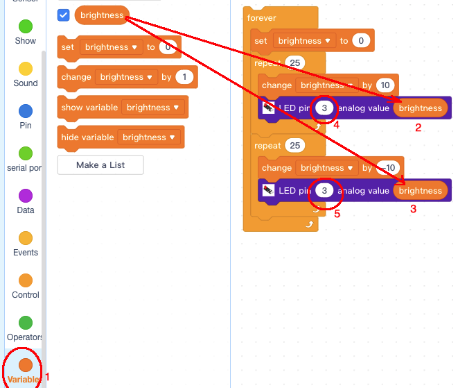
Step 7) Click Variable, then add 2 pcs brightness blocks to replace the 255 value in analog value field, also change LED pin number from 1 to 3 :
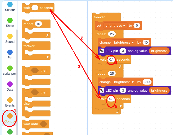
Step 8) Click Control, then add 2 pcs wait seconds block below LED pin blocks, change waiting time from 1 to 0.1 seconds:
Step 9) Click Events and add a when Arduino UNO starts up block in the top of all blocks:
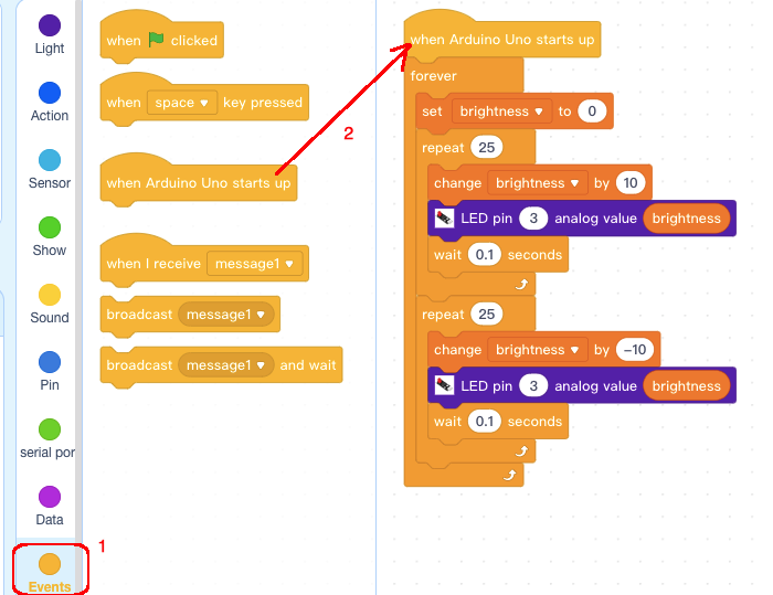
Now all the programming blocks have been completed! From above picture, the logic is pretty straightforward:
When Arduino is started, computer will enter a dead loop which will gradually increase LED brightness in D3 from 0 to 255, then gradually reduce its brightness from 255 to 0. each cycle period will take about 5 seconds.
Upload the program to Arduino
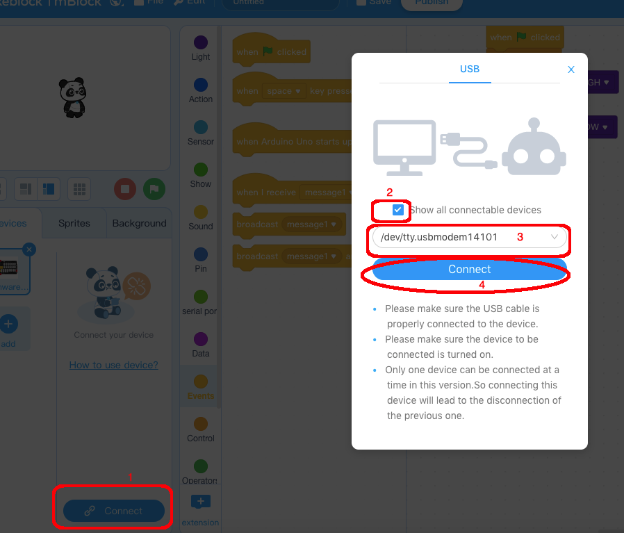
1)you need click the Connect button in the bottom of the mBlock software, you will see a USB window pop up,
2) select Show all connectable device check box , then a device drop-down menu will show up,
3) select your Arduino port from device drop-down menu
4) click Connect button to connect your PC to Arduino
5)After you PC is connected to Arduino UNO board, please click Upload button in the bottom of your software, then the code will be uploaded to Arduino UNO board:
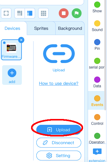
Now the LED in D3 port will change its brightness in periodically .


