Objective:
In this project, we will get temperature and humid data from DHT11 and send it to Raspberry Pi, then display the temperature and humid on 16×2 LCD screen.
If you don’t know what is GPIO layout, check our tutorial How to read Raspberry Pi i/o pin diagram (GPIO pin graph)
Parts:
| 1 pc |
Raspberry Pi 2/3/zero x 1 |
 |
| 1 pc |
8GB MicroSD memory card x 1preinstalled Raspbian OS. |
 |
| 1 pc |
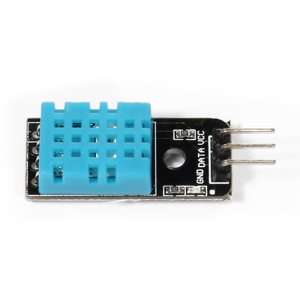
DHT11 Temperature/Humid Sensor x 1 |
 |
| 1 pc |
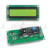
I2C 1602 LCD screen x 1 |
 |
| 1 pc |
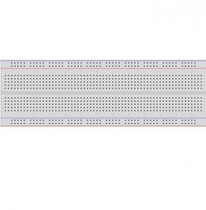
breadboard x 1 |
 |
| 1 pc |
GPIO breakout kit(optional) |
 |
Software/Hardware Installation and Configuration
Step 1)Raspbian should be upgraded to latest version in order to support RPI.GPIO module
Please run following commands in shell:
- sudo apt-get update
- sudo apt-get upgrade
Step 2)Enable I2C and SPI protocol
To enable the protocol, run shell command
sudo raspi-config
Then select Advance Options and enable I2C and SPI
After rebooting the Pi, we need to modify the module’s config file. Type the following command in terminal:
sudo nano /etc/modules
Add following two lines in modules file if they do not exist:
i2c-bcm2708
i2c-dev
Then Type Ctrl X and Yes to save the file.
Step 3) – Install smbus and i2c python library
Type following command in terminal:
sudo apt-get update
sudo apt-get install -y python-smbus i2c-tools
sudo reboot
After rebooting the system, type the following command in order to check software installation:
lsmod | grep i2c
You should see i2c_bcm2708 in a list, this means the library has been installed successfully. Otherwise you might need to find another Raspbian OS MicroSD card and repeat Step 2 and 3.
Step 4)Raspberry Pi ,I2C 1602 LCD and DHT11 sensor pin connection
| LCD Pin |
Description |
Pi Function |
RasPi Pin |
| GND |
GND |
GND |
pin 6 or pin 39 |
| VCC |
+5V/3.3v |
+3.3V |
pin 2 |
| SDA |
SDA |
GPIO 02 |
pin 3 |
| SCL |
SCL |
GPIO 03 |
pin 5 |
| DHT11 DATA pin |
GPIO 14 |
pin 8 |
| DHT11 +VCC pin |
+3V |
pin 1 |
| DHT11 GND(-) |
GND |
pin 6 |
Circuit Graph:
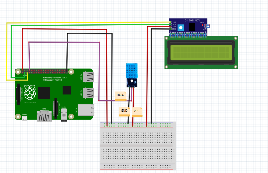
Caution: Unlike Arduino board 5V input voltage, Raspberry GPIO pin accept only 3 Volt. Wrong voltage input might damage the Pi board. Please be very careful!
Step 5) Testing Hardware
Depending on your Raspberry Pi version, please run one of following commands in terminal:
sudo i2cdetect -y 1
or
sudo i2cdetect -y 0
You should see something as follows:
0 1 2 3 4 5 6 7 8 9 a b c d e f
00: — — — — — — — — — — — — —
10: — — — — — — — — — — — — — — — —
20: — — — — — — — — — — — — — — — —
30: — — — — — — — — — — — — — — — 3f
40: — — — — — — — — — — — — — — — —
50: — — — — — — — — — — — — — — — —
60: — — — — — — — — — — — — — — — —
70: — — — — — — — —
If you can only see “– — –” sign in the list without any numbers, it means either your circuit connection is wrong or your software is not properly installed.
Please take special attention on the “3f” in above result, this is the i2c address of your LCD, it might be other value such as 27. If the value is not 3f, you need change line 18 of file “pi-dht11-i2clcd.py” (you need download this file in Step 6 with wget –no-check-certificate command)
Step 6) download python code
Please typing following shell commands to download python file(dht11.py):
sudo wget http://osoyoo.com/driver/dht11.py
a) If your LCD i2c address shows 3f, pls type following shell commands to download python file(pi-dht11-ic2lcd.py)
sudo wget http://osoyoo.com/driver/pi-dht11-i2clcd.py
b) If you get other number in the step 5(not 3F), pls type following command in shell window
sudo nano pi-dht11-i2clcd.py
then copy python code and paste the code into pi-dht11-ic2lcd.py.
you need change line 18 of file “pi-dht11-i2clcd.py” (I2C_ADDR = 0x3f, use your number to replace 3f)
Then Type Ctrl X and Yes to save the file. and press enter
Finally, run following command in shell window:
sudo python pi-dht11-i2clcd.py
If you can not see the text clearly in LCD, use a screw driver to adjust the brightness screw(on the back of 1602 LCD) until the display is ok.
Video Demo:


I was uncertain of 3V vs 5V for the LCD’s vcc connector. It says the Pi function is 3V but should be connected to pin 2 which is 5V. I selected pin 1 which has 3.3V to be safe. LCD had a very weak contrast even if adjusted to maximum.
The LCD gets much better contrast when connected to 5V and it appears not to damage the Pi board.
The LCD need to work with 5V GPIO.
k well having issues. Was successful in previous module in getting LCD to display text. So figured when I came here it would be a piece of cake. But for some reason I get nothing on the LCD. It lights but no text from the DHT11. Changed the one line to 0x27 instead of 0x3f as my address query came up with 27. So I am stumped as to why the DHT11 is not communicating
k so just went thru and made sure the DHT11 was good and was able to get text to SSH with Temp and Humidity readings.
So there is a disconnect somewhere.
Note: did not change any wiring on the breadboard or GPIO. also this is being done on a PI 3 don’t know if that is some of the cause as I have heard and foundout that there is discrepencies between calls in Pi2 and Pi3.
Just saying! Gonna take a break for a while. Head is spinning thinking about what could be going on or not going on.
okay figured it out. had used GPIO 4 instead of GPIO 14 works great now. Only need to look at code and see where I can add conversion function to get Farenheit instead of Celsius
This me too. Did ya figure out how to get to Fahrenheit?
I keep getting the error no module named dht11 … Any ideas?
Hi,
Thanks for providing this code, it was nice to actually get it working the first try. I downloaded everything and got it working good. Then I tried changing the Lcd code portion of the python code I downloaded (big mistake but not really if I can learn something from this) and then I started to get unrecognisable charters on the Lcd. So then I put ‘sudo python pi-dht11-i2clcd.py’ into terminal and enter and it would/does work properly for a minute or so then it’ll scramble the text again.
So what I did was to edit the text of the python code by entering ‘sudo nano pi-dht11-i2clcd.py’ and I erased all the code there and re-pasted the program back into terminal but am still getting the same results? Does anyone know what could be happening? And do I have to go through the whole process again and re-download everything? I don’t know what to do next.
If I do start all over again what do I have to get rid of before re-installing everything again?
Any help will be very much appreciated.
Thanks
jessey
It’s kind of useless to post anything here. There’s no support here by the looks of it. That’s a shame…