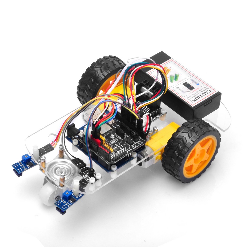
Welcome to the first lesson of OSOYOO 2WD Robot Car Starter Kit!
In this “Hello World” version lesson, we will install the most important framework of the robot car and program the car to do some simple movements. If you have passed the test movement of this lesson, it means Arduino, motor control module, motors, batteries, chassis, and wire connections between these parts are all functioning well.
As your experiments in future lessons are all based on the framework of Lesson 1, it is very essential to test the installation and sample code in this Lesson properly.
Hardware Installation
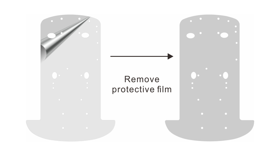
Remove the protective film from the back of the chassis.
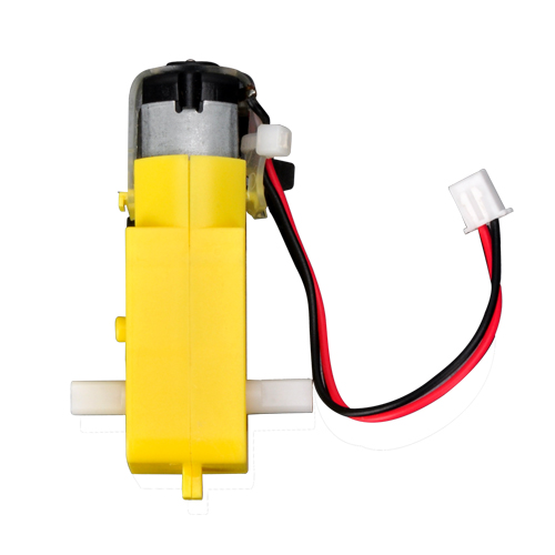
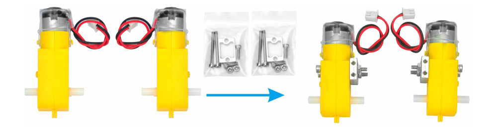
1 )Motors
Accessories:
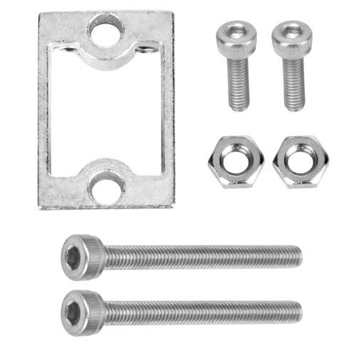
Motor Holder Set x2
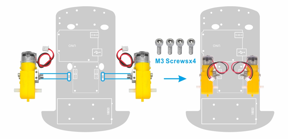
Install 2 motors on the chassis with the motor holders
Notice
Please install it on the side of the motor wires
Keep the end with the screw holes facing up
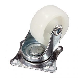
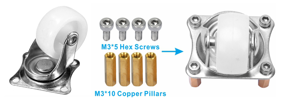
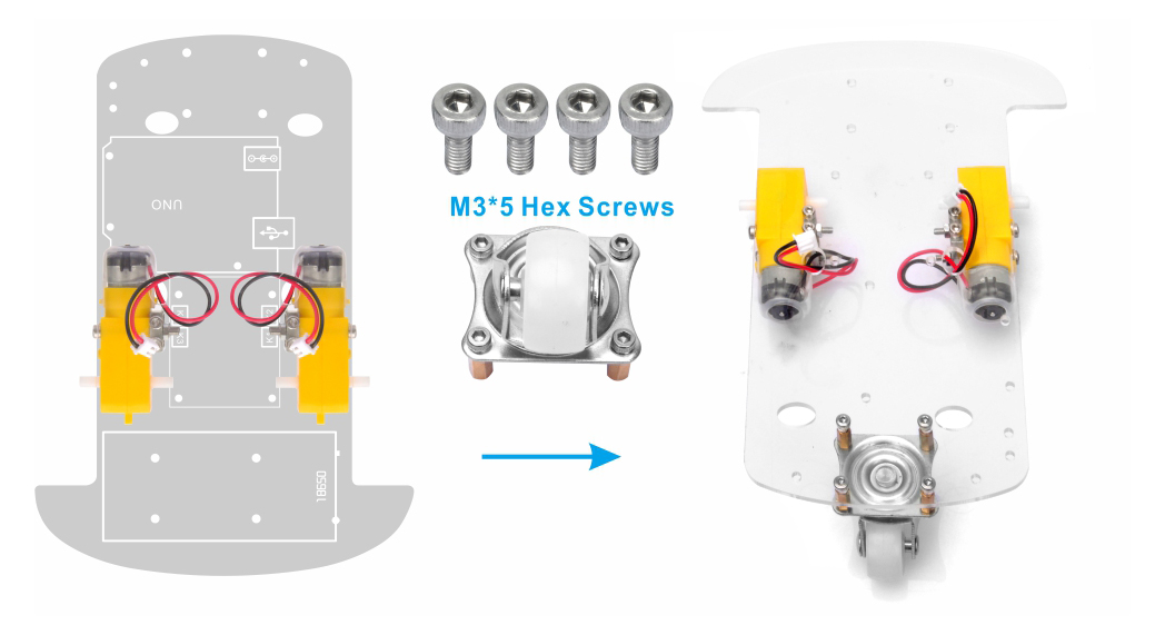
2) Universal Wheel and Wheels
Accessories:
M3*10 Double Pass Copper Pillar x 4
M3*5 Hex Screw x 8
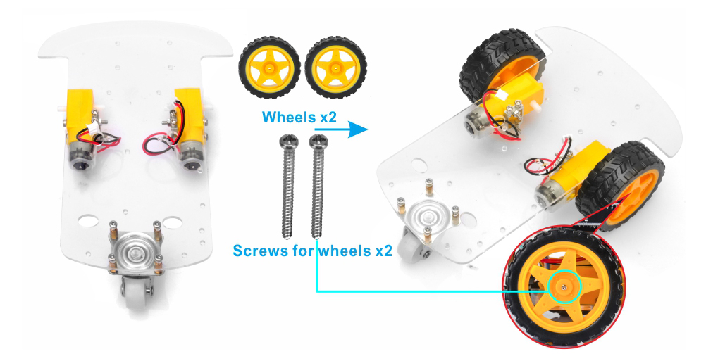
Screws for wheels x 2
Install the wheel on the chassis with M3*10 Double Pass Copper Pillars and M3*5 Hex Screws, then install the two wheels onto the motors.
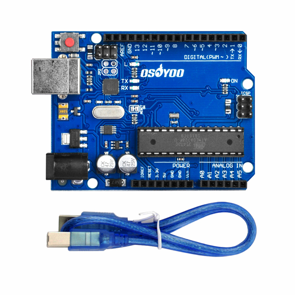
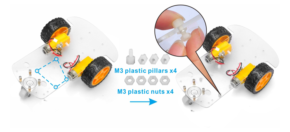
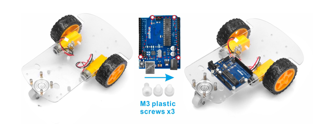
3) Install OSOYOO UNO Board
Accessories:
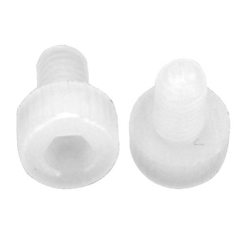
M3*6 Plastic Screw x 3
M3 Plastic Nut x 4
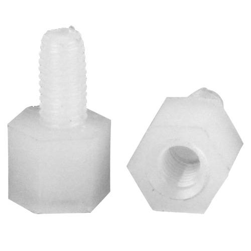
M3*5+6 Plastic Pillar x 4
Fixed the OSOYOO UNO board on the surface of the chassis with the M3 screws and nuts
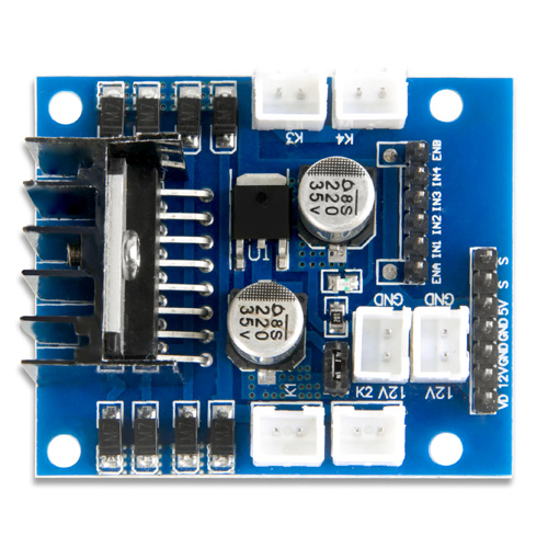
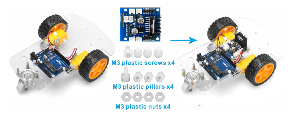
4) OSOYOO Model-X Motor Driver Module
Accessories:
M3*6 Plastic Screw x 4
M3 Plastic Nut x 4
M3*5+6 Plastic Pillar x 4
Fixed the OSOYOO Model-X motor driver module on the surface of the chassis with the M3 screws and nuts
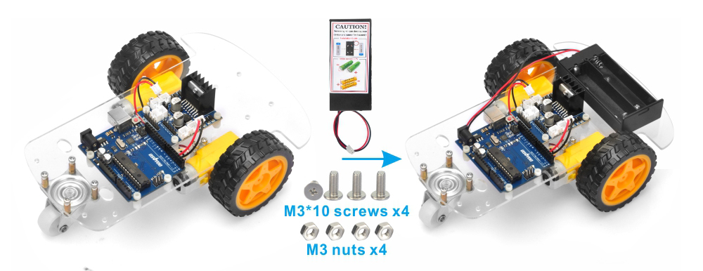
5) Battery Box
Accessories:
M3*10 Screw x 4
M3 Nut x 4
Fixed the battery box on the surface of the chassis with the M3 screws and nuts.
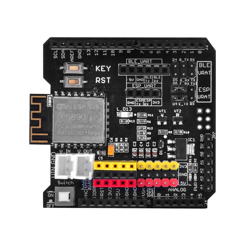
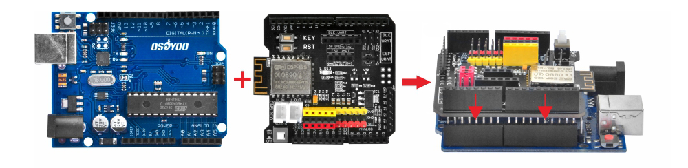
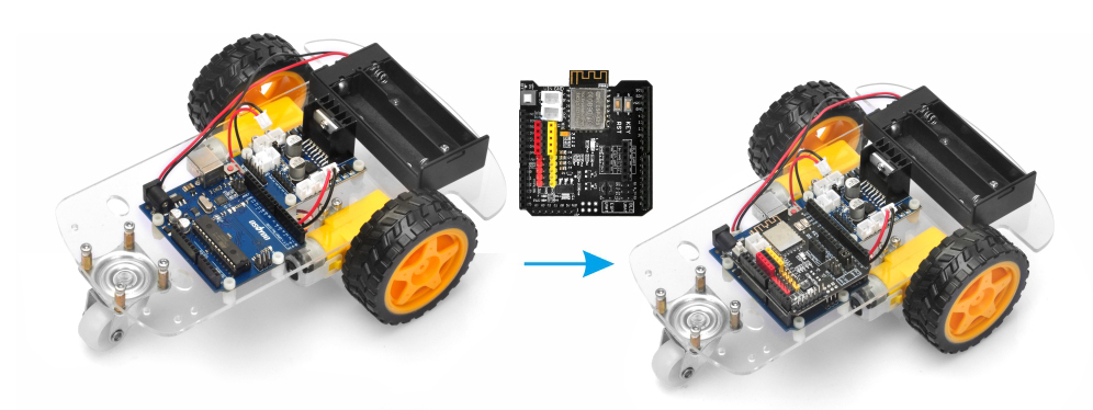
6) Insert Wifi Shield into UNO Board
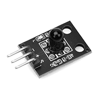
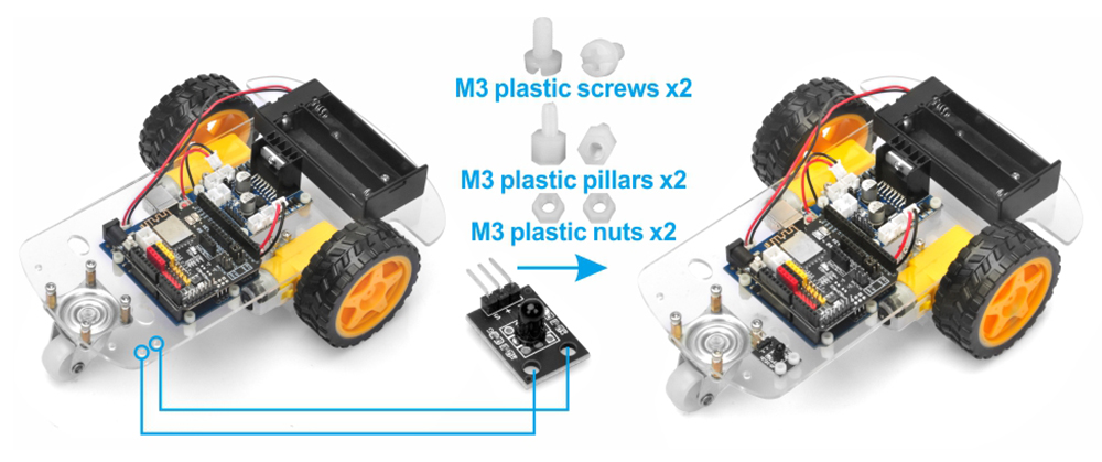
7 ) IR Receiver
Accessories:
M3*6 Plastic Screw x 2
M3 Plastic Nut x 2
M3*5+6 Plastic Pillar x 2
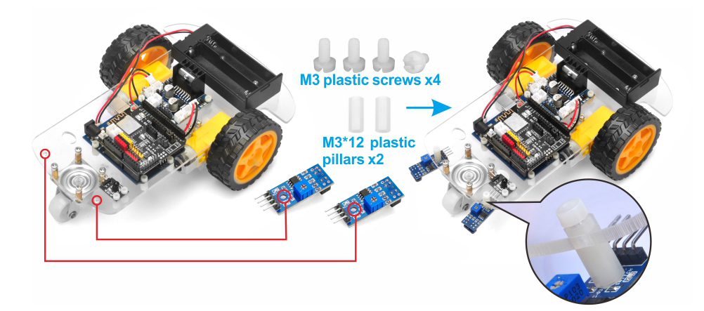
8 ) Tracking Sensor Module
Accessories:
M3*6 Plastic Screw x 4
M3*12 Plastic Pillar x 2
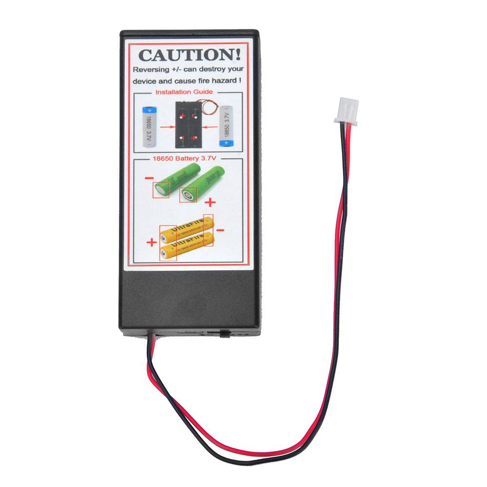
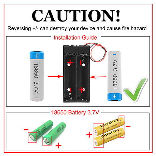
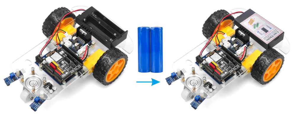
9 ) Battery
Notice: check the box instruction and make sure polar direction is correct, otherwise it can destroy your device and cause fire hazard.
Please keep the switch of the battery box to OFF.
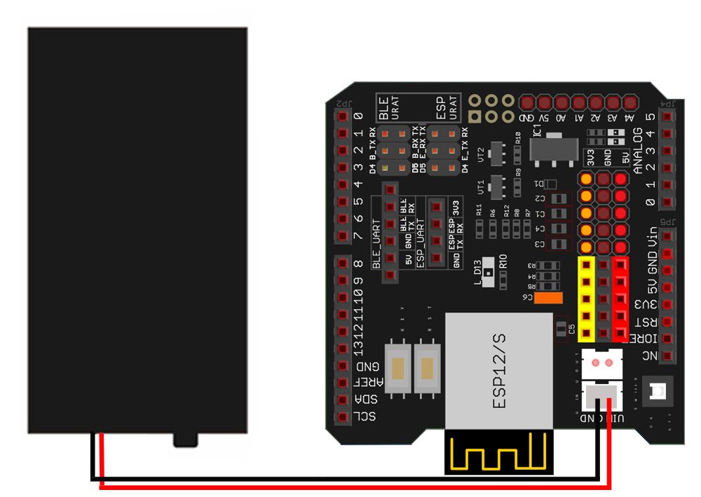
Wire Connection
Connect Battery Box to Wi-Fi Shield
:
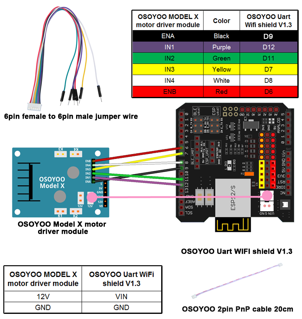
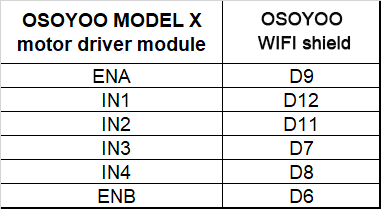
2. Connect the OSOYOO Model-X and WiFi Shield for Arduino UNO as shown below:
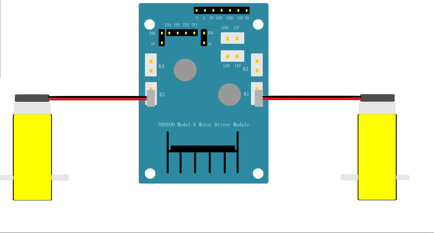
3. Connect OSOYOO Model-X Motor Driver Module with 2 motors
The right motor connected to K1 or K2, the left motor connected to K3 or K4 as shown below:
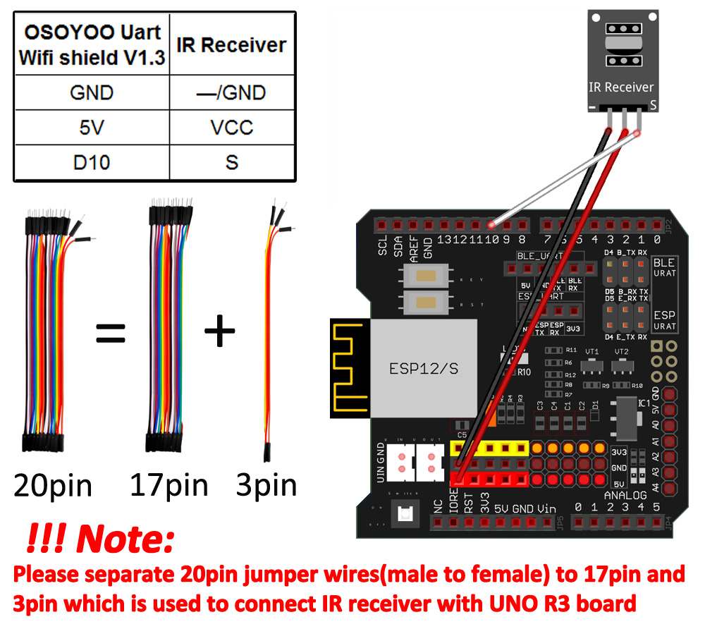
4. Connect OSOYOO UART Wi-Fi Shield with IR Receiver:
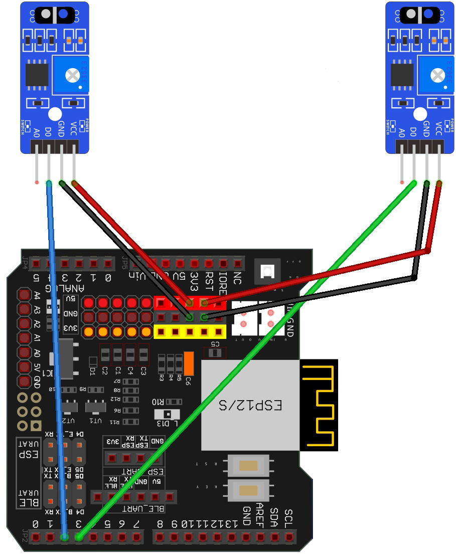
5. Connect OSOYOO UART Wi-Fi Shield with the tracking sensor:
The Lest Tracking Sensor
Tracking Sensor
Sensor Shield V5.0 for Arduino UNO
VCC
5V
GND
GND
DO
S2
AO
Not Connected
The Right Tracking Sensor
Tracking Sensor
Sensor Shield V5.0 for Arduino UNO
VCC
5V
GND
GND
DO
S3
AO
Not Connected
Software Installation
Notice: Shut off your battery or Unplug your power adapter when upload sketch code to Arduino.
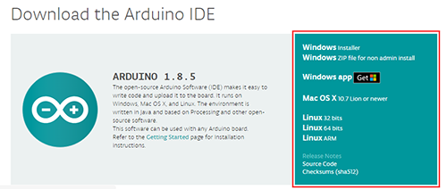
Step 1:
Install latest Arduino IDE (If you have Arduino IDE version 1.18.19, please skip this step).
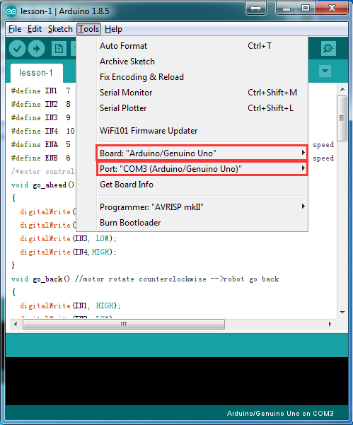
Connect UNO R3 board to PC with USB cable, open Arduino IDE, choose corresponding board/port for your project
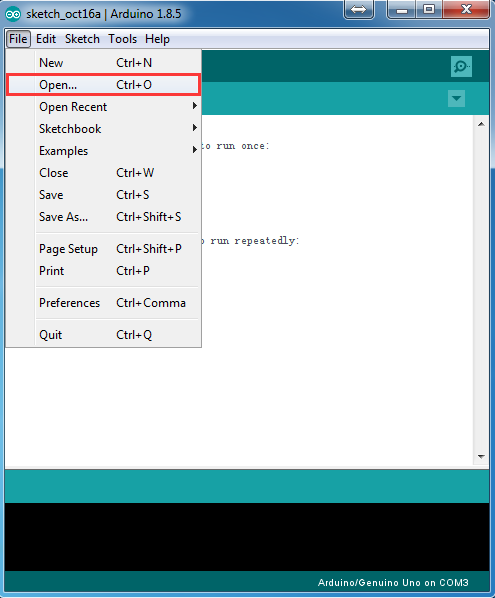
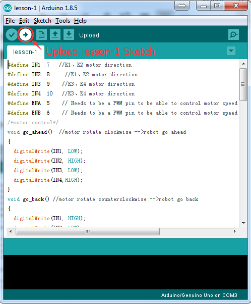
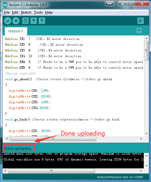
Step 4:
Click file -> click Open -> choose code “lesson1.ino”, load the code into Arduino, and then upload the sketch to the board.
Code Explanation
Below is the interface definition between OSOYOO Model-X and arduino
Notice: ENA and ENB should connect to PWM port, IN1/IN2 control Right Motor rotating direction,
IN3/IN4 control Left Motor rotating direction
#define speedPinR 9 // RIGHT PWM pin connect MODEL-X ENA
#define RightMotorDirPin1 12 //Right Motor direction pin 1 to MODEL-X IN1
#define RightMotorDirPin2 11 //Right Motor direction pin 2 to MODEL-X IN2
#define speedPinL 6 // Left PWM pin connect MODEL-X ENB
#define LeftMotorDirPin1 7 //Left Motor direction pin 1 to MODEL-X IN3
#define LeftMotorDirPin2 8 //Left Motor direction pin 1 to MODEL-X IN4
#define SPEED 140
#define RIGHT_SPEED 140
The below functions can control the car forward, backward, stop, turn right and turn left:
Disconnect Arduino from PC, put 2 fully-charged 18650 battery into battery box (check the box instruction and make sure polar direction is correct, otherwise it can destroy your device and cause fire hazard). Please install your battery as per the following instruction:
Put the car on the ground, open the power switch on the battery box, open the power switch on the Wi-Fi Shield.
The car should go forward 1 seconds, then go backward 1 seconds, then left turn for 1 seconds, then right turn for 1 seconds, then stop.
If the car does not move as per above-mentioned result, you should check your wire connection, battery voltage (must over 7.2v).
Troubleshooting
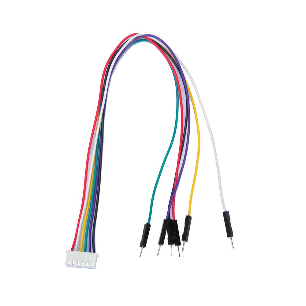
If, after running the Lesson 1 code, you notice that one side wheels are not turning, or one side wheels can only move forward but not backward, or only backward but not forward, the issue is likely a loose or broken wire in the 6-pin cable connecting to the Model X board.
Here is the solution:
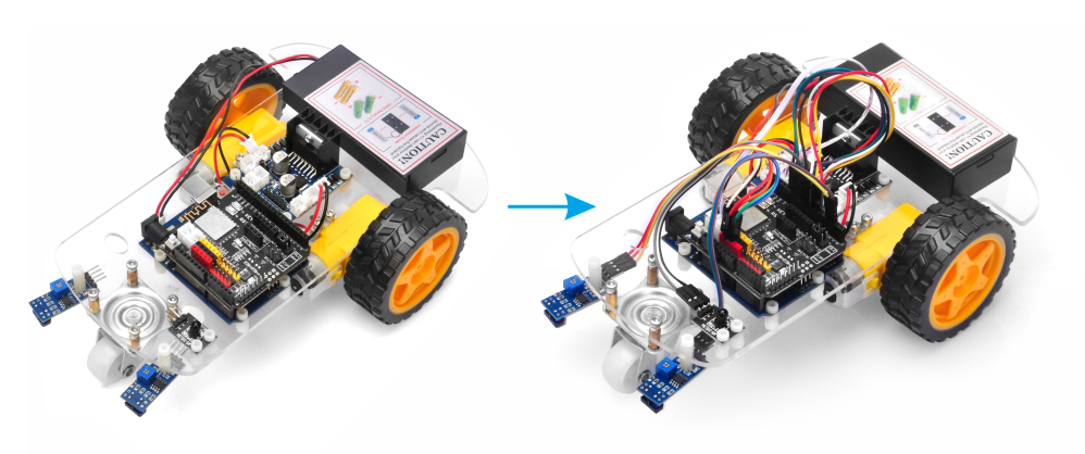
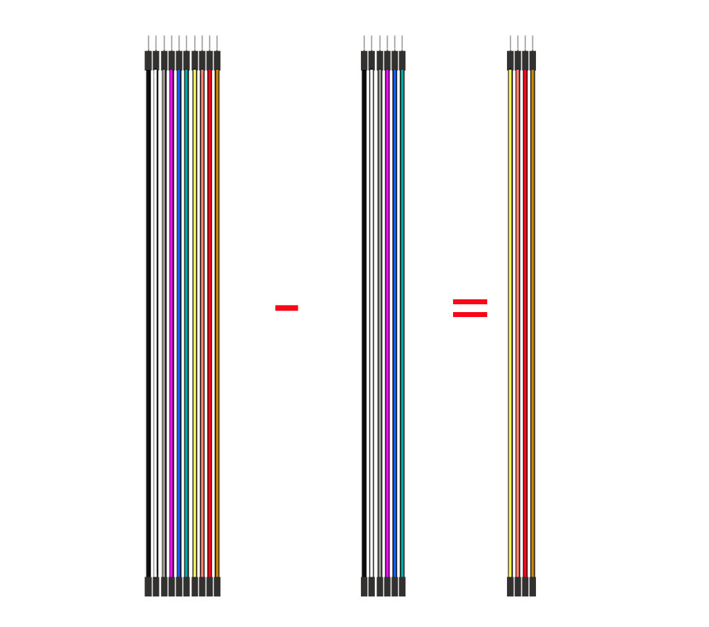
Step 1: Disconnect the 6-pin cable that connects the Model X board and the Arduino board.
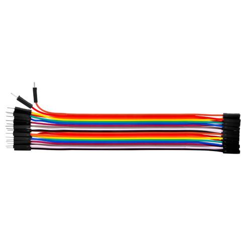
Step 2: Locate six (6) single spare Female-to-Male jumper wires from your kit (any color is fine).
Step 3: Use these six single jumper wires to manually reconnect the Model X pins (ENA, IN1, IN2, IN3, IN4, ENB) to the corresponding pins on the Arduino as per previous model x wire map
Step 4: Retest the Lesson 1 code to see if the issue is resolved. If the problem still exists, you can send your problem detail to [email protected] and our tech support team will help you.


 :
: