Note: ALL OSOYOO Products for Arduino are Third Party Board which is fully compatitable with Arduino
Introduction
The OSOYOO IR Track Sensor is essentially an IR LED and an IR detector. It works by transmitting a beam of IR light downward toward the surface. In this lesson, we will show you how the IR Track Sensor works and how to use it with the Osoyoo basic board.

Preparations
Hardware
- Osoyoo basic Board (Fully compatible with Arduino UNO rev.3) x 1
- IR Track Sensor x 1
- Jumpers
- USB Cable x 1
- PC x 1
Software
- Arduino IDE (version 1.6.4+)
About OSOYOO IR Track Sensor
The OSOYOO IR Track Sensor is essentially an IR LED and an IR detector. The IR emission tube of track sensor constantly emits infrared light. Since the black absorbs light, when the IR emission tube shines on a black surface, the reflected light is less and so less IR rays are received by the receiving tube. It indicates the resistance is large; then the comparator outputs high and the indicator LED goes out. Similarly, when it shines on a white surface, the reflected light becomes more. So the resistance of the receiving tube is lower; thus, the comparator outputs low and the indicator LED lights up.
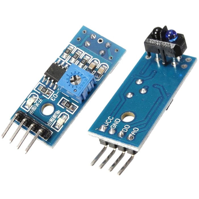
When the infrared transmitter emits rays to a piece of paper, if the rays shine on a white surface, they will be reflected and received by the receiver, and pin D0 will output low level; If the rays encounter black lines, they will be absorbed, thus the receiver gets nothing, and pin D0 will output high level.
This acts like a simple switch when it gets close to a white / black object. You can adjust the sensitivity with the potentiometer. It uses a LM393 Comparator chip and track sensor for clean outputs.
Sensitivity: About 1 inch (2.5cm) from white paper, about 1 cm from a person’s finger.
Examples
IR Line tracking
In this experiment, we will use an IR track sensor module and the on-board LED to build a simple circuit to make a tracking line. Since the LED has been attached to pin 13, connect the pin D0 to digital pin 2 of the board. When the tracking sensor detects reflection signals (white), the LED will be on. Otherwise, it will be off (black line).
Note: The sensitivity of the infrared sensor is adjustable – you may adjust it by the potentiometer.
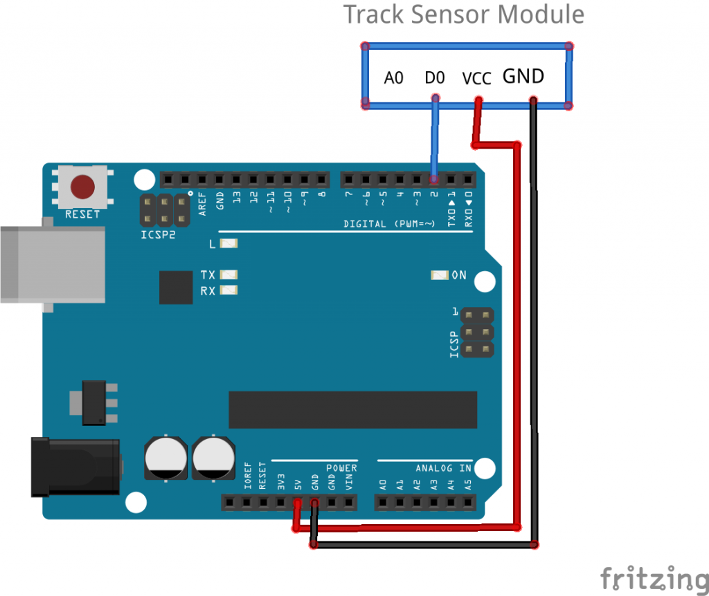
Connection
Build the circuit as below digram:
| OSOYOO basic board |
Track Sensor |
| +5V |
VCC |
| GND |
GND |
| D2 |
D0 |
Code Program
After above operations are completed, connect the board to your computer using the USB cable. The green power LED (labelled PWR) should go on.Open the Arduin IDE and choose corresponding board type and port type for you project. Then load up the following sketch onto your Arduin.
const int trackingPin = 2; //the tracking module attach to pin 2
const int ledPin = 13; //pin13 built-in led
void setup()
{
  Serial.begin(9600);
  pinMode(trackingPin, INPUT); // set trackingPin as INPUT
  pinMode(ledPin, OUTPUT); //set ledPin as OUTPUT
}
void loop()
{
  boolean val = digitalRead(trackingPin); // read the value of tracking module
  if(val == HIGH) //if it is HiGH
  {
    digitalWrite(ledPin, LOW); //turn off the led
    Serial.println("Detect: Black!");
  }
  else
  {
    digitalWrite(ledPin, HIGH); //turn on the led
    Serial.println("Detect: White!");
  }
}
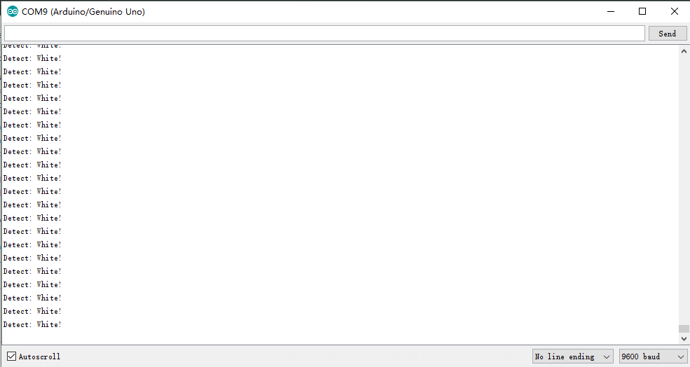
Running Result
A few seconds after the upload finishes, set it down on a piece of paper with a dark line (at least ½” wide). You may use a Sharpie Marker, electrical tape, or dark paint. When the module gets on a black line, it output high and the corresponding LED stays off, the Serial Monitor output: “Detect: Black!”;

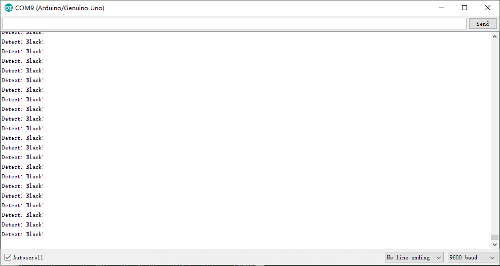
when it meets a white area, it outputs low and the LED lights up, the Serial Monitor output: “Detect: White!”.
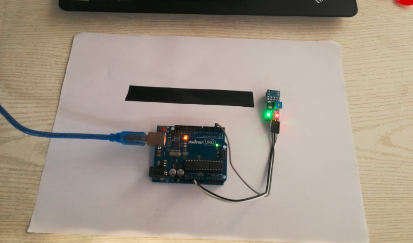
Note: The black line should be wider than the IR track sensor.


