


| Buy from US |
Buy from UK |
Buy from DE |
Buy from IT |
Buy from FR |
Buy from ES |
Buy from JP |
 |
 |
 |
 |
 |
 |
 |

In this lesson, we will show how to control 4 LEDs and make them work as a running light flow.

- A laptop or Desktop PC which runs Windows or Mac computer
- OSOYOO Magic I/O Shield for Arduino x1
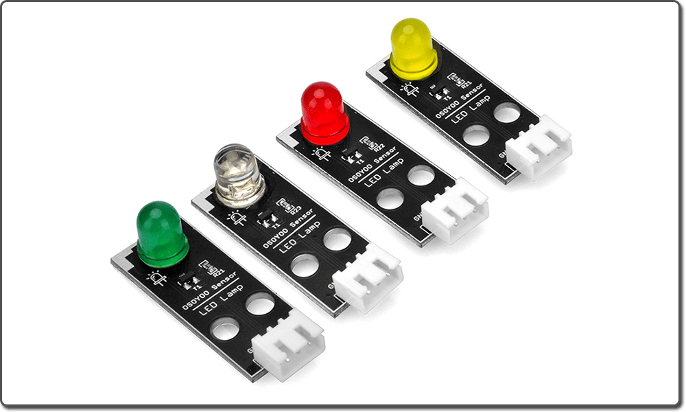
- Red LED Module x 4
- OSOYOO 3-Pin PnP cable x 4
- USB Cable x 1


Firstly, please plug Osoyoo Magic I/O shield into UNO board as following:

Then connect the LED module to the ports of the Magic I/O shield with four 3-pin PNP cables as below:
White – D2
Yellow – D3
Red – D4
Green – D5

Note:
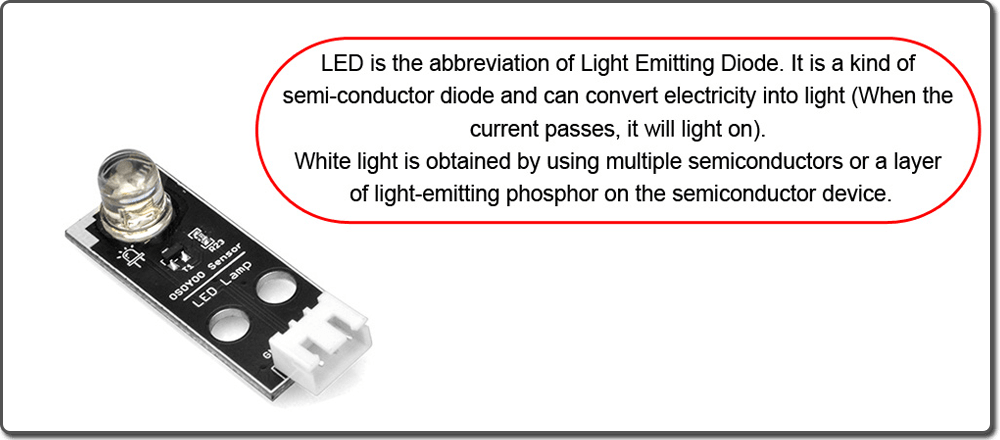
You should NOT connect a normal LED between 5V and GND pins in Arduino without a resistance. First, This will cause too much current passing through LED and burn it out. Second, the LED polarity is wrongly connected(i.e Positive Pin connected to GND pin) will also damage the LED.
To solve such problem. we designed OSOYOO LED module which has a build-in resistance to limit the current and fixed polarity socket to avoid these mistakes. In this project, we will use OSOYOO LED module. You can also download joker123 on this site and keep having fun gambling and winning.

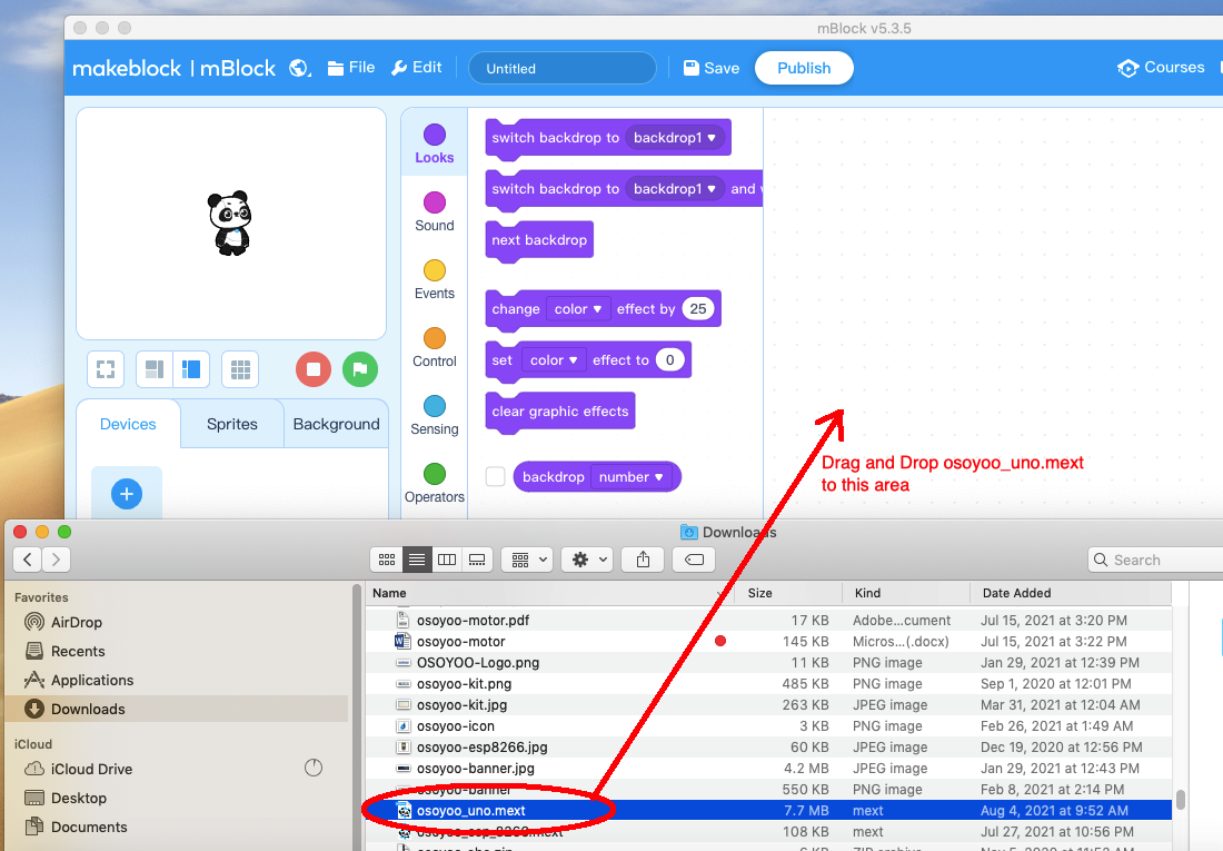
Step 1) If you haven’t install mBlock software in your PC, please read Lesson 1, download and install the software.
Step 2) Run the mBlock PC software by double click the lovely Panda icon. Drag and Drop osoyoo_uno_mext file(downloaded in Step 1) to mBlock software as following:
Now you will see a new device firmware in mBlock, see following picture:
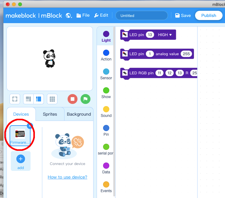
Now mBlock software and OSOYOO_UNO device firmware have been successfully installed in our PC!
Make our program with blocks
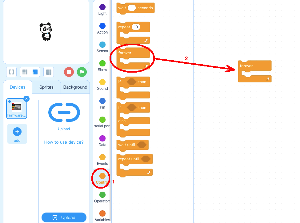
Step 1: Click Control, then Drag and drop Forever block to programming area as following:
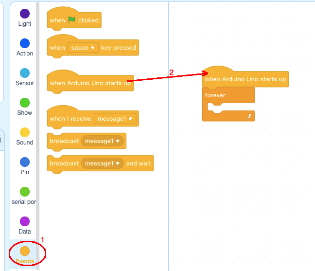
Step 2: Click Events, add when Arduino Uno starts up block to the top:
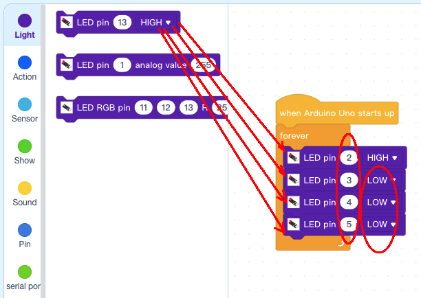
Step 3: Click Light , drag 4 pcs LED pin 13 High blocks to forever loop,
then change pin number from 13 to 2,3,4,5, change Pin 3,4,5 value to LOW:
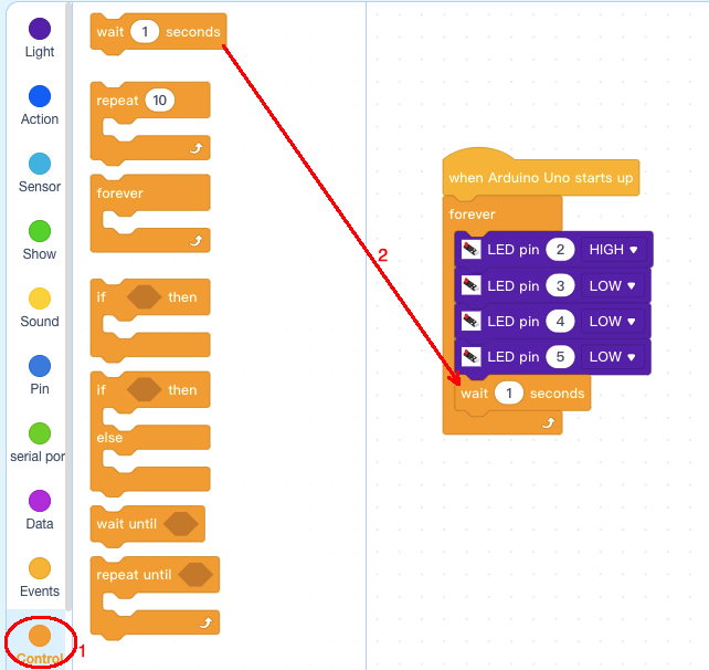
Step 4: Click Control, Add wait 1 seconds blocks below LED blocks:
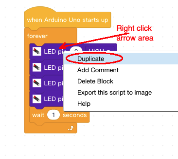
Step 5: Right Click LED 2 Block, Then select duplicate to copy five inner blocks :
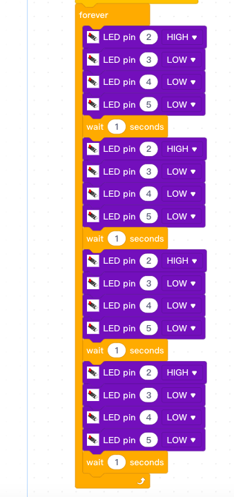
Step 6: Paste the duplicated blocks below wait 1 seconds block and repeat the procedure 4 times, then change the pin value as per following picture :
 |
Change LED pins HIGH Value =>> |
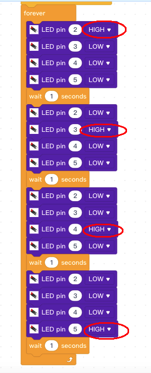 |
Now all the programming blocks have been completed! From above picture, the logic is pretty straightforward:
When Arduino is started, computer will enter a dead loop which will gradually increase LED brightness in D3 from 0 to 255, then gradually reduce its brightness from 255 to 0. each cycle period will take about 5 seconds.
Upload the program to Arduino
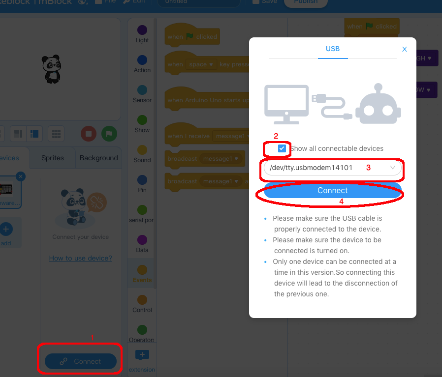
1)you need click the Connect button in the bottom of the mBlock software, you will see a USB window pop up,
2) select Show all connectable device check box , then a device drop-down menu will show up,
3) select your Arduino port from device drop-down menu
4) click Connect button to connect your PC to Arduino
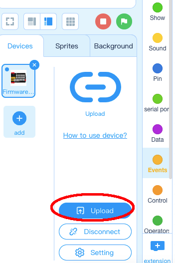
5)After you PC is connected to Arduino UNO board, please click Upload button in the bottom of your software, then the code will be uploaded to Arduino UNO board:
Now the LEDs in Pin 2,3,4,5 will turn ON/OFF like a running light flow .


