Since year 2021, Raspberry Pi board has some supply chain issue and not available anymore for regular customer. So many people are looking for an alternative solution for Raspberry Pi board.
There are many options of Single Board Computer(SBC) in the market. In this tutorial, we want to introduce Rock Pi 4 board as the substitute of Raspberry Pi in robot control projects.
Rock Pi 4 OS installation
Rock Pi 4 use Debian buster OS, Please download image file from:
https://github.com/radxa-build/rockpi-4b/releases/download/main-ce723808/rockpi-4b-debian-buster-xfce4-arm64-20220506-0320-gpt.img.xz
Image Burner:
We high recommend balenaEtcher image burner, please visit https://www.balena.io/etcher/ to get the software for MacOS or Windows.
If you are using Windows, you can also use Win32DiskImager utility
Once you have burned the OS into your SD card, insert the SD card into your Rock Pi 4, your OS will show login page, please use default username rock and default password rock to login. We highly recommend you use passwd command to change password after login .
Now please set your wifi ssid and password with following commands:
sudo nmcli dev wifi connect "your-wifi-ssid" password "your-wifi-password"
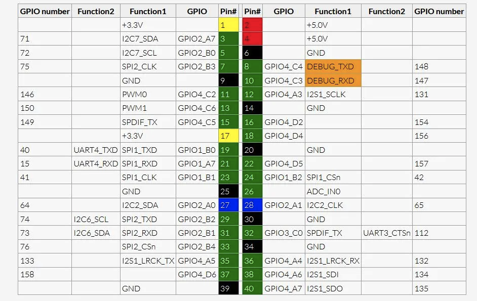
GPIO Pin table :
Following table shows the GPIO number of each physical pin of Rock Pi. We will use the GPIO number in python programming.
Install Python GPIO coding library periphery by following terminal command:
sudo apt-get update

sudo apt-get install python3-pip
sudo pip3 install python-periphery
sudo apt-get install wget
Sample Project 1: Blink
In this project, we will make a flashing LED to test Rock Pi GPIO output function.
Connect Circuit:
Connect the positive leg of a LED to GPIO 73 (physical pin# 31 in above pin table), connect the negative LED leg to GND through a 200 ohm resistor .
Sample Code:
from periphery import GPIO
import time
LED_Pin=73
LED_GPIO=GPIO(LED_Pin,"out")
while True:
    try:
        LED_GPIO.write(True)
        print("LED ON!")
        time.sleep(1)
        LED_GPIO.write(False)
        print("LED OFF!")
        time.sleep(1)
    except KeyboardInterrupt:
        LED_GPIO.write(False)
        break
    except IOError:
        print("error")

LED_GPIO.close()
You can also directly download the code file by typing following command:
wget https://osoyoo.com/driver/rockblink.py
Now you can run above code by following command:
sudo python3 rockgpioblink.py
You will see the LED in GPIO 73 will blink.
Sample Project 2: Use button to control LED in project 1
In this project, we will use a push button to control LED in Project 1.
Connect Circuit:
Keep LED to GPIO 73 (physical pin# 31 in above pin table) unchanged.
Connect one leg of a push button to 3.3V connect another leg of push button to GPIO pin 153 (physical pin 16) and also connect this leg to GND through a 1M pull-down resistor.
Sample Code:
from periphery import GPIO
import time
LED_Pin=73 #GPIO pin 73 physical pin 31
Button_Pin=154 #GPIO pin 154 physical pin 16
LED_GPIO=GPIO(LED_Pin,”out”)
BUTTON_GPIO=GPIO(Button_Pin,”in”)
while True:
try:
buttonvalue=BUTTON_GPIO.read()
print(buttonvalue)
if (buttonvalue==True):
print(“LED ON!”)
LED_GPIO.write(True)
else:
LED_GPIO.write(False)
print(“LED OFF!”)
except KeyboardInterrupt:
LED_GPIO.write(False)
break
except IOError:
print(“error”)
LED_GPIO.close()
You can also directly download the code file by typing following command:
wget https://osoyoo.com/driver/rockgpiotest.py
Now you can run above code by following command:
sudo python3 rockgpiotest.py
Test the project:
Push down the button in GPIO 73, your LED in GPIO 153 will turn on, release the button, the LED will turn off.


