OVERVIEW
The Osoyoo Breakout Board for 30P ESP32 & ESP8266 is a versatile and user-friendly expansion board tailored for ESP32 and ESP8266 modules with 30-pin headers. Designed with a rich set of interfaces, high-quality components, and comprehensive tutorial resources, this breakout board is ideal for both beginners and experienced developers. Whether you’re working on educational projects, prototyping, or advanced development, this board provides robust support and flexibility.
Since there are different specifications of 30P ESP32 & ESP8266 modules in the market, we added two sets of 2*15p row mother, it can be compatible with 0.9/1.0/1.1 feet row pin spacing modules, which greatly improves its compatibility, if you need a 38pin esp32 breakout board, you can click this link.
It adds LED indicators for each GPIO port, so you can use the indicators to know the status of the pins and easily verify your prototype code without even wiring it up.
Features
- Compatibility:
- Supports most 30-pin ESP32 and ESP8266 modules.
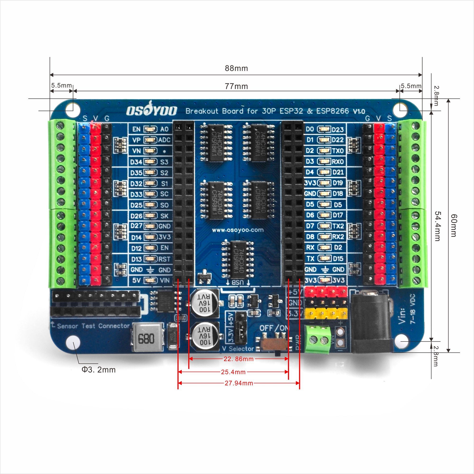
- Includes two sets of 2×15-pin headers for enhanced compatibility with a variety of modules with pin widths of 0.9/1.0/1.1 inches (22.86/25.4/27.94 mm).
- LED Indicators:
- Each GPIO port has an LED indicator to display the status (high/low) of the pins, making it easier to debug and verify code without additional wiring.
- Independent LED, The LED status is driven by the chip in the Breakout instead of the ESP32/ESP8266 GPIO so the GPIO will not be affected.
- Power Protection:
- Features a reverse power protection circuit to prevent damage if the power is connected incorrectly.
- On-board power switch for convenient control.
- Power Options:
- Dual power output: 5V/2A and 3.3V/500mA, providing ample power for servos and sensors.
- Automatic power switching between USB and external power sources.
- External power input via screw terminals or DC jack (7-12V recommended).
- Voltage Selection:
- The V_Selector jumper allows you to choose between 3.3V and 5V for the V output pin. By default, the V pin is set to 3.3V output. Ensure the correct voltage is selected to avoid damaging the board or connected devices.
- Easy Connectivity:
- 2.54mm pitch pin headers and screw terminals for seamless connection to sensors, servos, and other peripherals.
- On-board 3-pin interfaces with V and GND pins for easy sensor or servo connections.
TECH SPECS
| Name |
OSOYOO_IO_Breakout_Board_for_30P_ESP32 & ESP8266_v.1.0 |
| Operating Voltage |
5V |
| VIN Input Voltage (recommended) |
7-12V |
| VIN Input Voltage (limit) |
7-18V |
| ADC Channels |
18 |
| PWM Digital I/O Pins |
16 |
| Pinhead number |
30 |
| Power Switch |
Yes |
| External Power Output |
5V/2A 3.3V/500mA |
| Options for power input |
USB/DC005–2.1/Screw terminal/Male pinheads |
| On-Board LED Indicators |
28 |
| Length |
88 mm |
| Width |
60 mm |
| Weight |
45 g |
DIAGRAM
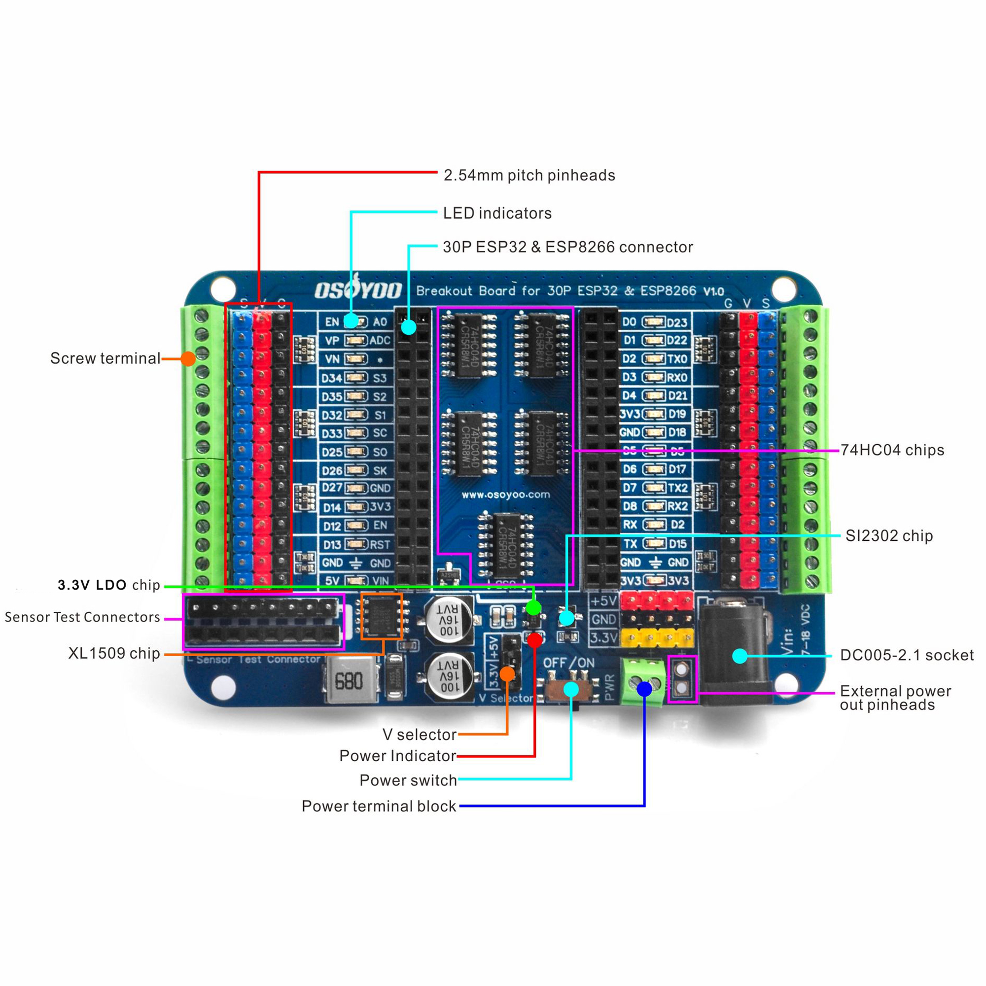
- 30P ESP32 & ESP8266 connector: Two sets of 2×15-pin row headers for compatibility with various module pin spacings. Ensure correct orientation when inserting the module to avoid damage.
- LED indicators: LEDs light up when GPIO pins are high and turn off when low.
- 2.54mm pitch pinheads: The S terminal directly connects to the ESP32 & ESP8266, it comes with V and GND pins for easy connection to sensors or servos.
- Screw terminal: Connect to all GPIO headers with 2.54mm pitch.
- XL1509 chip: DC/DC converter supporting 5V/2A output.
- LDO Chip: LDO regulator for 3.3V/500mA output.
- V selector: Jumper cap to select between 3.3V and 5V for the V pin.
- Power switch: On-board switch for easy power control.
- Power terminal block: We recommend using a 7-12V DC power supply.
- DC005-2.1 socket: We recommend using a 7-12V DC power supply.
- External power out pinheads: Can be used with an external DC power supply or to power other devices
- SI2302 chip: N-Channel MOSFET, here we use it in a power supply screw terminal anti-reverse circuit
- 74HC04 chips: It is a hex inverter. We use it to connect each I/O port to control the corresponding indicator.
- Sensor Test Connectors: 8-pin male and female connectors make testing sensor modules easy.
Important Notes
- Voltage Selection:
- By default, the V pin is set to 3.3V. Do not connect 5V devices to the GPIO pins when using this setting.
- If using an external power supply, ensure the jumper cap on the V_Selector is correctly placed for the desired voltage (3.3V or 5V).
- Power Supply:
- Do not use both the DC jack and screw terminal simultaneously to avoid damaging the board.
- If powering via USB, the V pin will not output voltage unless the jumper cap is removed from the V_Selector and connected to the S-3V3 pin.
- Assembly:
- Ensure the ESP32 or ESP8266 module is correctly aligned before powering the board to prevent damage.
ASSEMBLY
When inserting, please pay attention to the boards‘ orientation,ensure the ESP32 & ESP8266 is correctly connected before applying power to the power supply interface to avoid damaging the board due to misalignment.
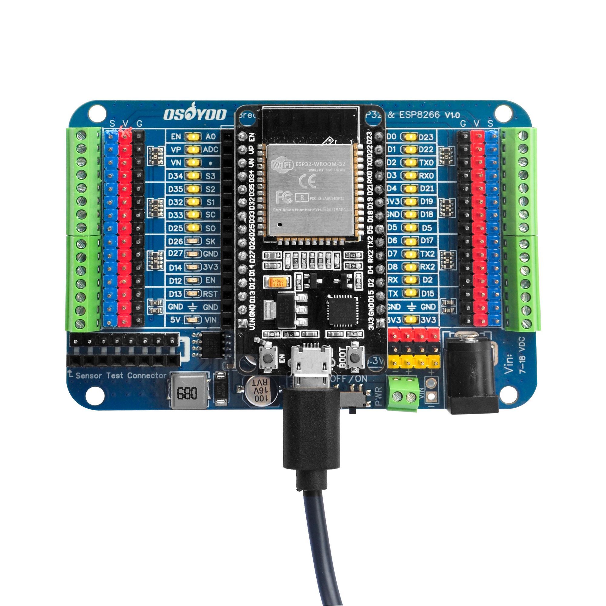
(The ESP32 & ESP8266 mocule is not included in this product, you will need to bring your own or buy it directly from the official website.)
Fritzing Part file download link:
https://osoyoo.com/public_html/driver/OSOYOO_Breakout_Board_for_Pico/2024009700-OSOYOO-Pico-IO.svg (ESP32 & ESP8266 30P fritzing pending upload)
DIMENSIONS
Resources
- Schematic: Download Schematic
- Dimensions: Download Dimensions
- Fritzing File: Download Fritzing File (ESP32 & ESP8266 30P breakout pending upload)
- Arduino Test Code:
- Component Datasheets:
- Related Links
Support
If you encounter any issues or have questions about using the OSOYOO Breakout Board, feel free to contact our technical support team for assistance.


i try the output pins for 5v but it is only 3.3v, i place the v selector on 5v
Are you using onboard USB power or DC power?