購入リンク
OSOYOOストアで購入
米国Amazonで購入
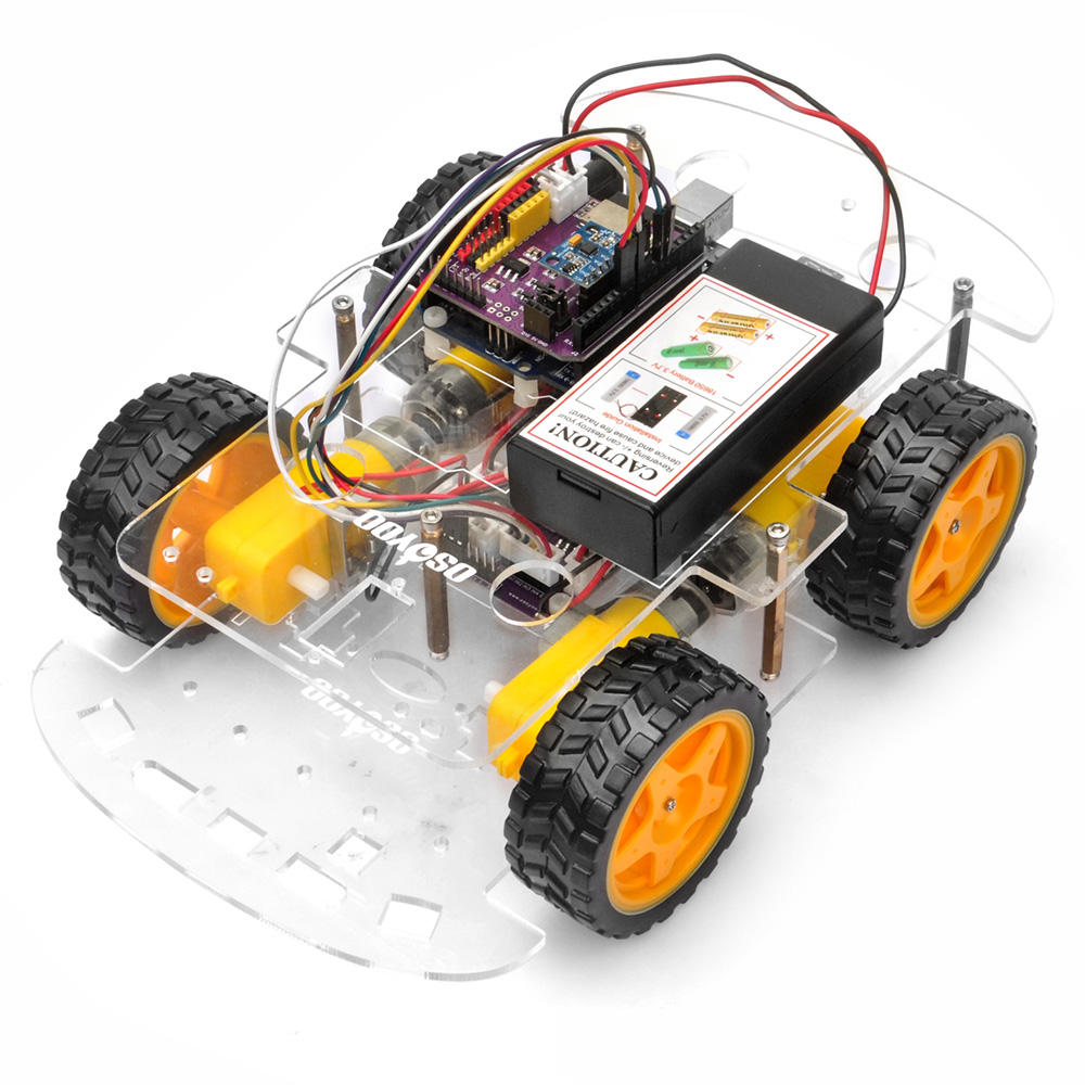
VIDEO 1 目標このチュートリアルでは、MPU6050 慣性計測ユニット(IMU)を使用して OSOYOO V3 ロボットカーの自律走行能力を高め、目標方向を維持する方法を解説します。MPU6050 は 3 軸モーションセンサーで、角速度(ジャイロスコープ)と線形加速度(加速度計)のデータを提供し、ロボットが進行方向を自動補正できるようにします。このレッスンでは、センサーフュージョン技術と PID 制御アルゴリズムを使った安定した直進走行の実現方法を学びます。
2 必要なパーツとデバイスこのレッスンでは次のコンポーネントが必要です。作業を始める前にご用意ください。
番号
画像
デバイス
数量
アクセサリ
リンク
1
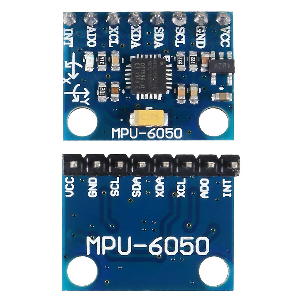
MPU6050 3軸ジャイロスコープ
1
こちらから購入
3 MPU6050:動作原理MPU6050 は 3 軸ジャイロスコープと 3 軸加速度計を統合したセンサーです。ジャイロスコープは角速度を測定し、ロボットの X、Y、Z 軸まわりの回転速度を提供します。このデータを時間積分すると角変位(例:ヨー角)が得られます。ただし、ジャイロスコープの生データはドリフトが生じやすく、時間とともに小さな誤差が蓄積します。加速度計は線形加速度を測定し、重力に対するデバイスの向きを求めるために使用できます。加速度計は長期的には安定していますが、振動や急激な動きに非常に敏感であるため、生の姿勢データにはノイズが多くなります。
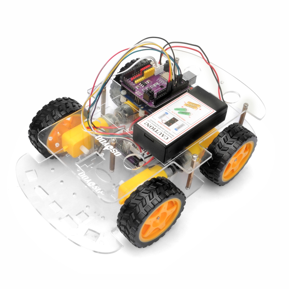
4 ハードウェアの取り付けステップ 1: ロボットカー レッスン 1 の説明に従って基本的なハードウェアを組み立ててください。レッスン 1 をすでに完了している場合は、そのままにしておいてください。
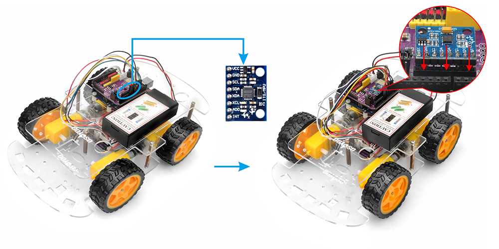
ステップ 2: 以下の図のように、MPU6050 モジュールをロボットシャーシにしっかり固定してください。(MPU6050 は I2C プロトコルで Arduino と通信します。必要な配線は SDA(シリアルデータ)と SCL(シリアルクロック)の 2 本のデータ線と、電源(VCC)とグランド(GND)のみです。)
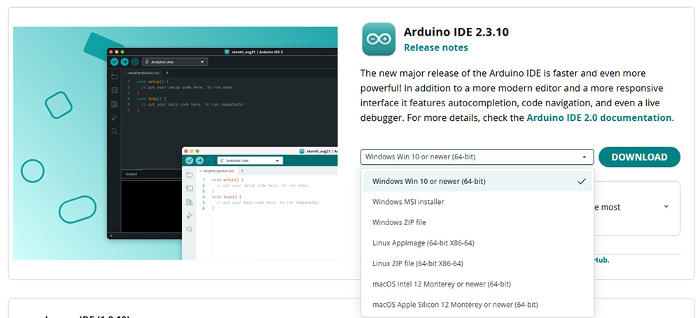
5 ソフトウェアのインストール1. Arduino IDE のセットアップ :最新版の Arduino IDE を https://www.arduino.cc/en/Main/Software?setlang=en からダウンロードしてインストールしてください。
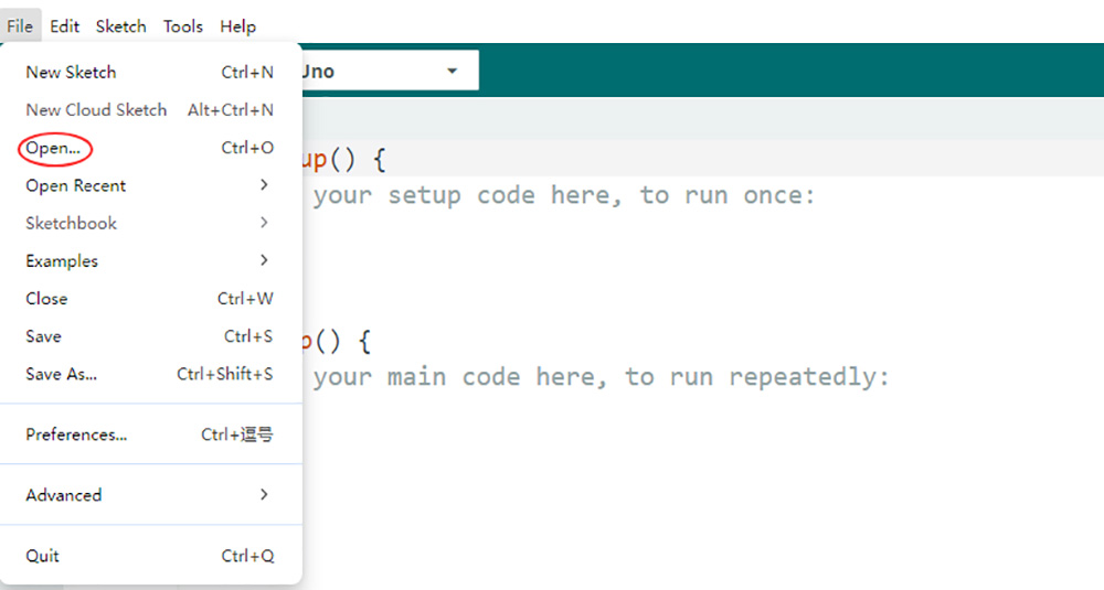
2. サンプルコードのダウンロード :レッスン 2 のサンプルコードをここからダウンロード してください。解凍すると v3car-lesson2 フォルダ内に v3car-lesson2.ino ファイルが見つかります。v3car-lesson2.ino を Arduino IDE で開いてください。
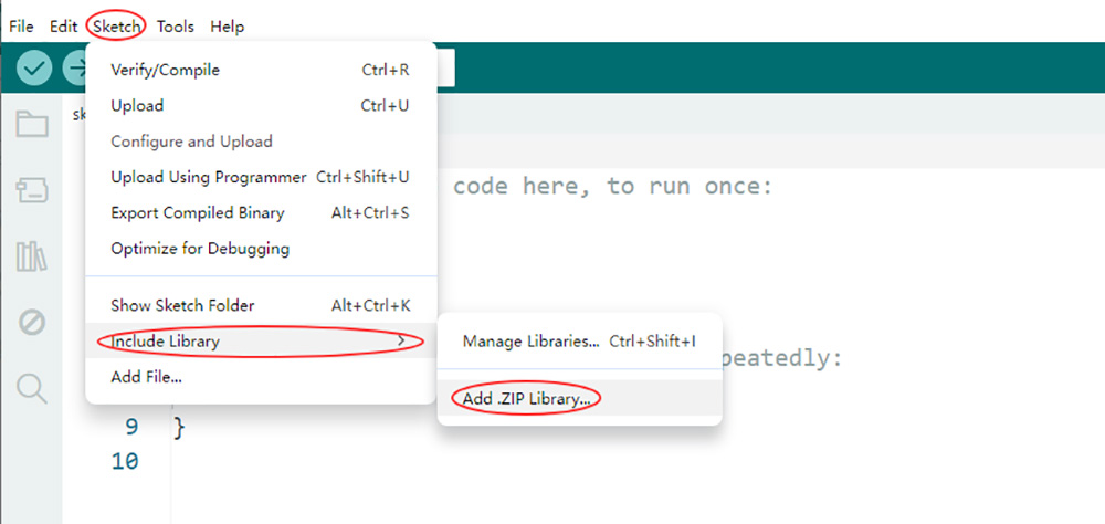
3. ライブラリのインストール https://osoyoo.com/driver/2wd/MPU6050_light.zip https://osoyoo.com/driver/2wd/PID.zip
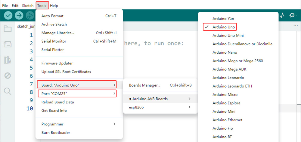
4. ボードとポートの選択 :OSOYOO Basic Board(Arduino UNO 互換)を USB ケーブルでコンピューターに接続します(重要:ボードを PC に接続する前に、ロボットカーの電源スイッチが OFF になっていて、バッテリーが取り外されていることを確認してください )。Arduino IDE を起動し、ツール > ボード で Arduino Uno を選択します。次にツール > ポート で正しいシリアルポートを選択してください。ポートがわからない場合は、OS のデバイスマネージャーを確認してください。
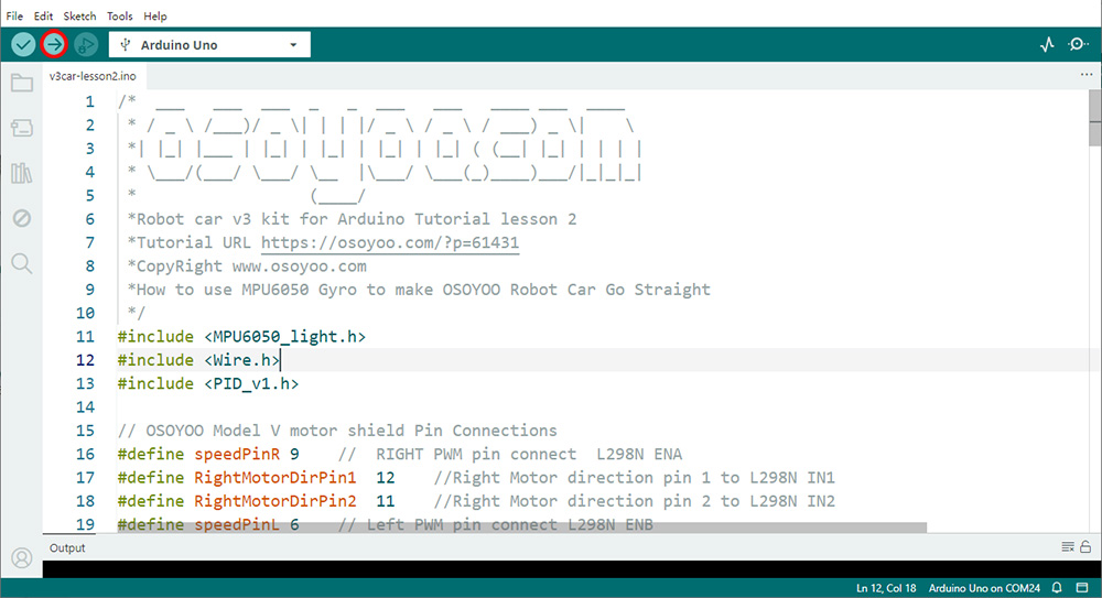
5. コードのアップロード :「マイコンボードに書き込む」ボタン(右矢印アイコン)をクリックして、スケッチをコンパイルし OSOYOO Basic Board に書き込みます。
6. Arduino が MPU6050 を認識しているか確認する
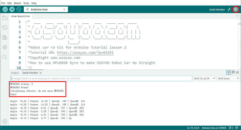
Arduino IDE 右上のシリアルモニタを開き、ボーレートを 9600 に設定すると、以下のように MPU6050 Found! と表示されるはずです。おめでとうございます!Arduino が MPU6050 を認識しています。カーをテストする準備ができました。
注意:「Failed to find MPU6050 chip 」と表示された場合、MPU6050 の配線に問題があります。次の点を確認してください: 1)MPU6050 の VCC/GND/SDA/SCL が、OSOLINK Wi-Fi/BLE I/O シールドに説明書どおり正しく接続されているか 2)Arduino の A4/A5 ピンと SDA/SCL ピンに他のケーブルが接続されていないか(ラインセンサープロジェクトでは A4/A5 がセンサーに使用されている場合があります)
6 走行テスト
VIDEO
カーを床に置いて電源を入れます。Arduino がジャイロスコープを初期化する間、カーはしばらく停止します。その後、直進します。足でカーを押して方向を変えると、自動的に元の方向に修正されます。
7 原理とコードの簡単な説明1)Move() 関数はカーの動きとステアリングをどのように制御しますか? move(speedL, speedR) 関数は、左右のホイールの回転速度を表す speedL と speedR の 2 つのパラメータを持ちます。速度値は -255 から +255 の範囲で、正の値が前進回転、負の値が後退回転を意味します。例えば、move(-50, 100) は左ホイールが速度 50 で後退、右ホイールが速度 100 で前進することを意味し、カーは急激に左折します。2)MPU6050 プログラミング入門 Direction 変数は、カーを床に置いた瞬間の向きを表します(前を向いていると仮定し、Direction を 0 に設定します)。loop() 関数の最初の数行の計算の後、カーの現在の向きが 129 行目の currentAngle 変数に格納されます。
3)PID とコードの入門:
a)基本的な考え方:PID とは何か?
車を運転していて、車線の中央に完璧に保つことを目標にしていると想像してください。それがまさにロボットに求めていること、つまり「まっすぐ前」の線に留まることです。
PID は、注意深い運転手のように機能する制御アルゴリズムです。ステアリングをどう切るかを判断するために、常に次の 3 つの問いを投げかけます:
P(比例): 今この瞬間 、車線中央からどれだけ離れているか?I(積分): ここ数瞬間 、ずっとずれ続けていたか?D(微分): 中央に向かって、またはそこから離れる方向に速すぎる速度 でずれているか?
これら 3 つの問いへの回答を組み合わせることで、PID コントローラーは滑らかで効率的なステアリング補正を行います。
b)コード内で PID 関数がどのように機能するか
この理論を PID_v1.h ライブラリとコードに直接結びつけてみましょう。
// We tell the PID controller what to watch and what to control.
PID myPID(&Input, &Output, &Setpoint, Kp, Ki, Kd, DIRECT);

Direction = 0; // Our TARGET is to have an angle of 0 degrees.
myPID.SetMode(AUTOMATIC); // Turn on the controller.
&Input:センサー読み値へのポインタ。コード内で Input は currentAngle です。PID コントローラーはこの値を継続的に読み取ります。&Output:結果へのポインタ。PID コントローラーは計算した補正値を Output 変数に書き込みます。&Direction:目標値へのポインタ。直進させたいので 0 に設定します。
// 1. We get the sensor reading and put it into the Input variable.
Input = currentAngle;

// 2. We call the compute function. This is where the PID magic happens!
myPID.Compute();

// 3. We use the result to control the motors.
int speedL = baseSpeed - Output;
int speedR = baseSpeed + Output;
move(speedL, speedR);
myPID.Compute() 関数はすべての計算を内部で処理します。呼び出されるたびに(ライブラリが SetSampleTime に基づいてタイミングを管理)、次の処理を行います:
Input 変数(currentAngle)の値を読み取る。誤差を計算する:error = Direction - Input。
比例項を計算する(Kp * error)。
積分項を計算して加算する(Ki * accumulated_error)。
微分項を計算して加算する(Kd * rate_of_error_change)。
すべてを合計して最終的な補正値を得る。
この最終値を Output 変数に書き込む。
Output が +15 の場合、ロボットは 15 単位の補正が必要です。片方のモーターを減速させ(baseSpeed - 15)、もう片方を加速させる(baseSpeed + 15)ことで、ロボットを旋回させて誤差を減らします。ロボットが完全に直進している場合、Input は 0、誤差は 0、Output は 0 となり、両モーターが baseSpeed で動作します。
4)Kp、Ki、Kd の調整方法(安定した走行のために)
まずここから: コード内で Ki = 0.0、Kd = 0.0 に設定します。振動しない(またはほとんど振動しない)安定した Kp 値を見つけます。おそらく 1.5 未満です。
(任意ですが推奨)センサーノイズを無視するために、ループに約 0.5 度の不感帯(deadband)を追加します。
Kp が安定したら、残りのオーバーシュートを減らすために Kd をゆっくり増やします。最後に、長期的なドリフトを除去するために Ki をゆっくり増やします。
8 応用とトラブルシューティング
モータードライバーの互換性: OSOYOO Model V モーターシールドが正しく配線されており、DC モーターの電流に対応できることを確認してください。配線の誤りや電力不足は不規則な動きの原因になります。電源の安定性: 電源の変動はモーターの性能と MPU6050 の測定値の両方に影響します。安定した電源を使用してください。機械的バランス: 重量が均等に分散され、ホイールが正しく整列したバランスの取れたシャーシは、直進性能を大幅に向上させ、PID コントローラーへの負担を軽減します。コードの最適化: より複雑なアプリケーションでは、MPU6050 のデータ取得レートと PID 計算頻度を最適化することで、マイクロコントローラーに過負荷をかけることなくリアルタイムの応答性を確保することを検討してください。
これらのガイドラインに従い、基本原理を理解することで、OSOYOO V3 ロボットカーを自律ナビゲーションのための優秀なプラットフォームに変え、より高度なロボティクスプロジェクトへの基礎を築くことができます。