Objective:
In this project, we will use GPIO port 21 (Pin 40) to output signals to LED and make it flashing ten times.
If you don’t know what is GPIO layout, check our tutorial How to read Raspberry Pi i/o pin diagram (GPIO pin graph)
Parts:
1 pc
Raspberry Pi 2/3/zero
1 pc
8GB MicroSD memory card preinstalled Raspbian OS.
1 pc
LED
1 pc
200 Ω resistance
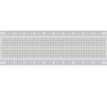
1 pc
breadboard
1 pc
GPIO breakout kit(optional)
Prerequisite:
1)Raspbian should be upgraded to latest version in order to support RPI.GPIO module
Please run following commands in shell:
sudo apt-get update
sudo apt-get upgrade
2)Enable I2C and SPI protocol
To enable the protocol, run shell command
sudo raspi-config
Then select Advance Options and enable I2C and SPI
You need to reboot to effect the configuration
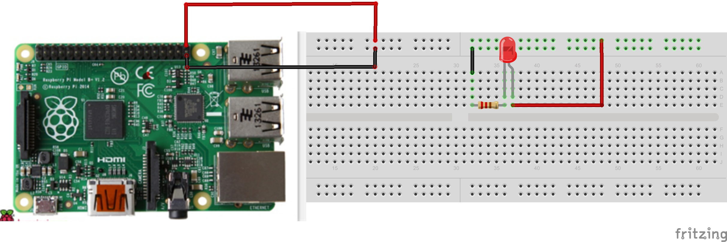
Assemble Circuit as per following graph:
Write python code
Run following command in shell window:
sudo nano testgpio.py
then copy python code and paste the code into testgpio.py
.
Then Type Ctrl X and Yes to save the file. and press enter
If you don’t want use nano to write code, You can also download above python file from our server by typing following shell command:


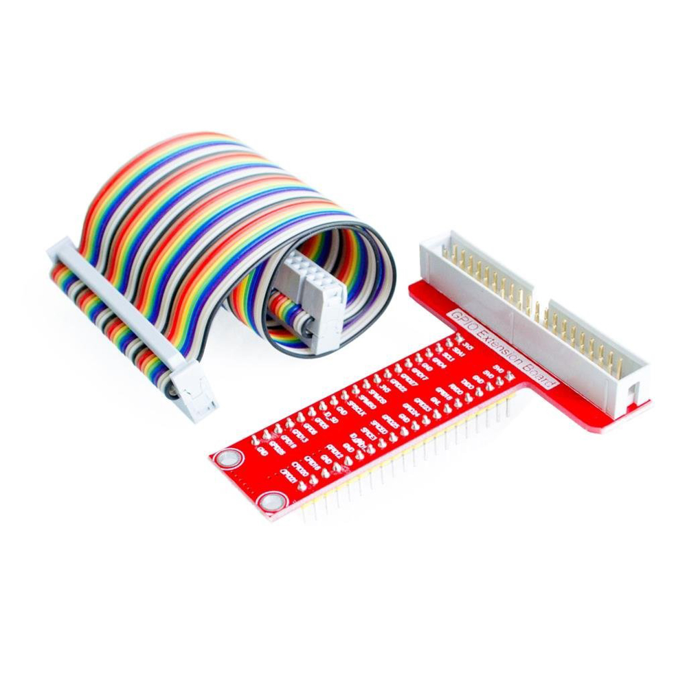
40ピンリボンケーブルをRaspberry Piに接続するときには注意が必要。
凸がある方をRaspberry Piの内側に向けて接続しないと、40ピンT型GPIO拡張ボードの説明と合わなくなる。
お世話になります。貴重なアドバイスありがとうございます。