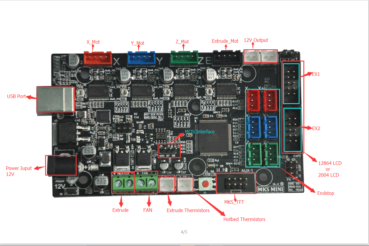
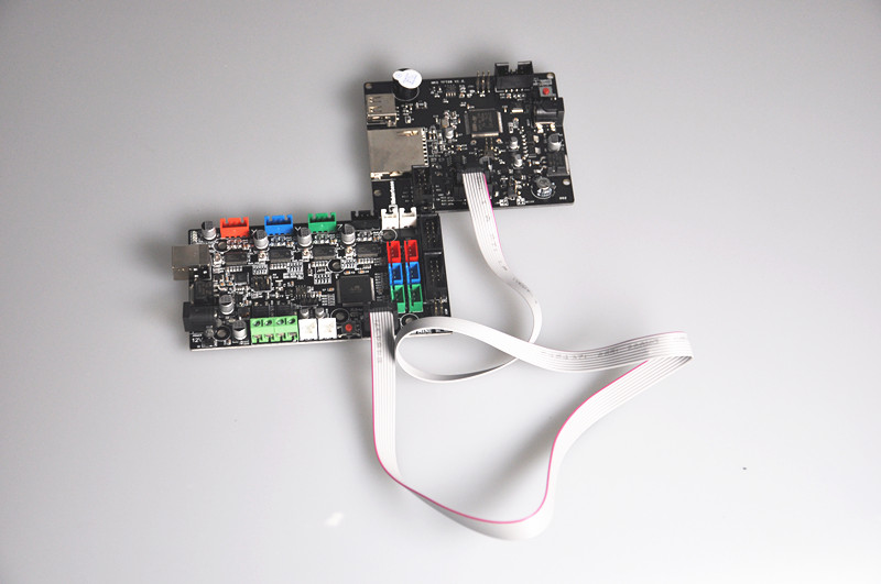
Picture 1: MKS MINI V1.2 Connection Graph:
Caution: Double check following two points before turn on the power
1)Before connect 12V power adapter, use a voltage meter to check the power is 12V and most important, the inner part(center)should be positive voltage 12v and outside part shoud be GND. If you connect wrong power voltage and direction, you may damage the MKS mini board and such damage will not be covered by manufacturer’s warranty.
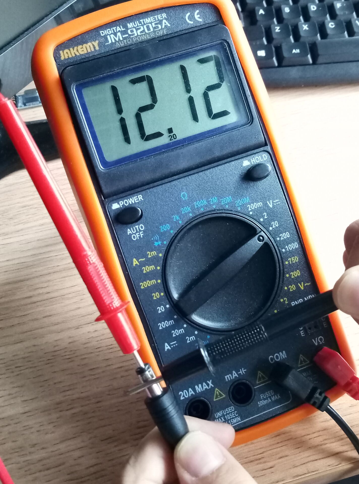
Following graph shows you how to verify power adapter’s voltage value and direction.
connect adapter to power(but do not plug it into MKS board),use a digital voltage meter to measure the output voltage of the adapter. You should use meter’s Red Pen to touch inner(center) part of adapter head and use black pen to touch the outside metal cover of adapter head. The value of meter should be around 12 voltage. If the value is negative, it means the adapter voltage direction is wrong, If the value is much bigger or smaller than 12V, you should change adapter.
Picture 2: Use voltage meter to verify power adapter output voltage correctness
2)Never plug or unplug any module or parts from MKS mini board when power is on. It might damage the board.
Sometimes you might need to adjust working current by change Potentiometer resistor value. You should turn of board power first, then use a screw driver to adjust potentiometer as per following picture.
Picture 3: Adjust working voltage
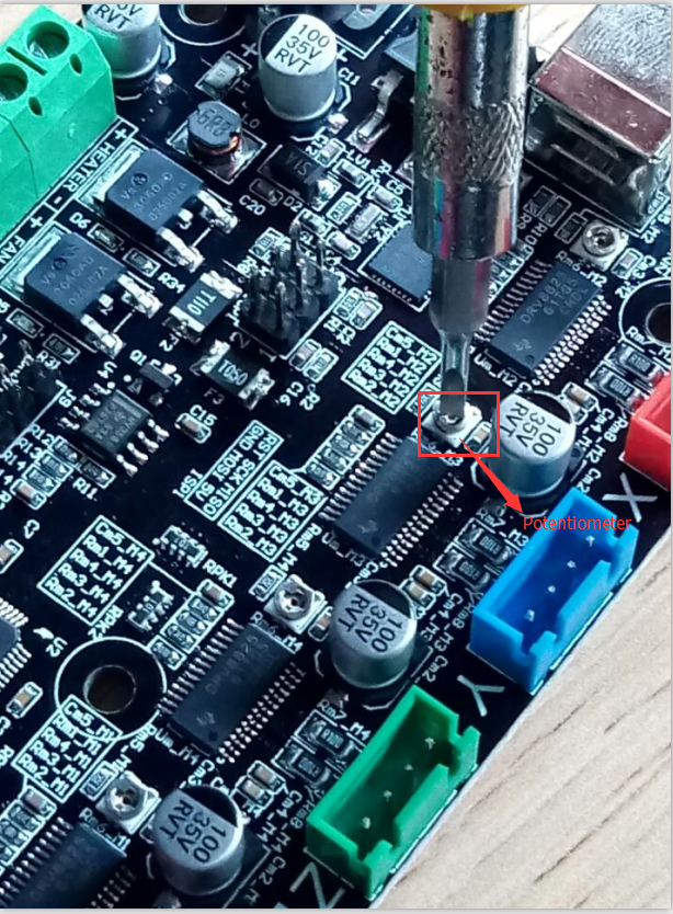
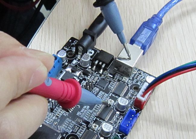
When screw driver turns potentiometer in clockwise direction, it will reduce the working voltage and vice versa. When testing working voltage, you should put the voltage meter RED (POSITIVE) pen onto the metal shell of potentiometer and BLACK(GND) pen on USB metal cover. Adjust potentiometer and make the voltage value to 0.65Volt. This is a recommend working voltage for the board. working long time under voltage over 0.65V might cause over heat and damage board.
Picture 4: measure working voltage
MKS MINI V1.2 motor driver chip DVR8825 has a maximum work load current Imax.
Imax = V_REF/0.5ohm, V_REF is the value you get from voltage meter in above step. If the V_REF is adjust to 0.65V , then Imax value is 1.3A(Normally we don’t suggest user to adjust V_REF close to 1.25V which might cause overhead damage).
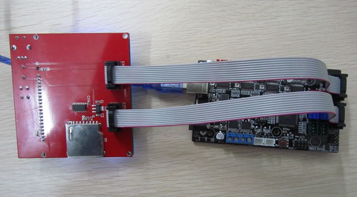
MKS-MINI is specially designed for single head 3D printer which does not have heat bed. If your 3D printer has heat bed, you need buy MKS MOS module and connect it to MKS MINI J9 port(see Picture 1 MOS Interface)
Picture 5: connect MKS Mini
Please take following steps to install the software in order to let your printer work properly.
Prerequisite: You should have connected your MKS MINI V1.2, LCD control panel and 3D printer properly(if you don’t know how to connect the circuit, check with your supplier or google the related topic).
Please be noted MKS board Z axis servo controller installation as following:
If printer only has one Z axis motor, connect this motor to the “Z” port. If printer has two Z axis motors, you need parallel connect them to “Z” port into MKS mini board.
Step 1) Install Arduino and driver(if you have already installed Arduino, please skip this step).
First, please download Arduino IDE from https://www.arduino.cc/en/Main/Software.
Step 2) use USB cable to connect MKS MINI V1.2 board with your PC. install driver automatically.
If driver can not be installed automatically, you can download the driver from following link:
https://osoyoo.com/driver/ftdi_ft232_drive.zip
Unzip above file and run the installation program
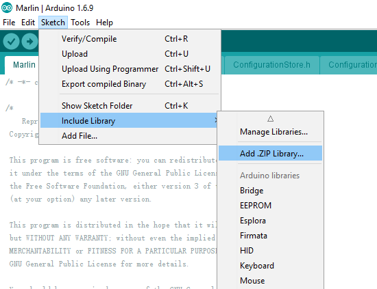
Step 3)Install U8glib library into Arduino IDE. If you have already installed U8glib, please skip this step>
First: Download U8glib library from kookye U8glib library .
Then, in Arduino IDE ->Sketch->Include Library->Add Zip Library , select the zip file you just downloaded and load into IDE. see following picture:

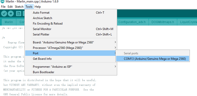
Step 4) In Arduino IDE->Tools->Board select Arduino Mega 2560:
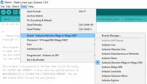
In Tools->Port select the COM port which associated with Arduino Mega2560(see picture below)

Step 5)Download Ramps1.4 board Marlin firmware as per your LCD screen type.
Unzip above file, you will see a folder called “Marlin”
In above Marline folder, there is Configuration.h file which defines some important hardware config setting values. Please read following instruction to change the Configuration.h and configuration_adv.h file according to your hardware situation:
A)If you connectMKS MINI V1.2 board with two Z axis servo motors, please make following changes,
In configuration.h line 248 to 253:
#define INVERT_X_DIR false // for Mendel set to false, for Orca set to true
#define INVERT_Y_DIR true // for Mendel set to true, for Orca set to false
#define INVERT_Z_DIR false // for Mendel set to false, for Orca set to true
#define INVERT_E0_DIR false // for direct drive extruder v9 set to true, for geared extruder set to false
#define INVERT_E1_DIR false // for direct drive extruder v9 set to true, for geared extruder set to false
#define INVERT_E2_DIR false // for direct drive extruder v9 set to true, for geared extruder set to false
in configuration_adv.h uncomment line 148 #define Z_DUAL_STEPPER_DRIVERS as following:
#define Z_DUAL_STEPPER_DRIVERS // disable this line if you have only one Z motor
B)If you connect MKS MINI V1.2 board with only One Z axis servo motors, please make following changes,
In configuration.h line 248 to 253:
#define INVERT_X_DIR false // for Mendel set to false, for Orca set to true
#define INVERT_Y_DIR true // for Mendel set to true, for Orca set to false
#define INVERT_Z_DIR false // for Mendel set to false, for Orca set to true
#define INVERT_E0_DIR false // for direct drive extruder v9 set to true, for geared extruder set to false
#define INVERT_E1_DIR false // for direct drive extruder v9 set to true, for geared extruder set to false
#define INVERT_E2_DIR false // for direct drive extruder v9 set to true, for geared extruder set to false
in configuration_adv.h disable line 148 #define Z_DUAL_STEPPER_DRIVERS as following:
//#define Z_DUAL_STEPPER_DRIVERS // disable this line if you have only one Z motor
Step 6)In Arduino IDE->File->Open, find Marlin Folder and open Marlin Arduino File(Marlin.ino)
Your IDE will compile the firmware and load it into board. There might be some warning error message during compiling, just neglect those message.
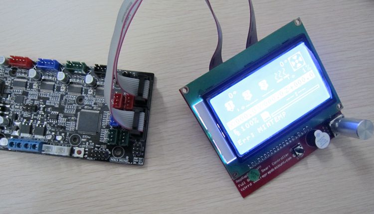
After the firmware is loaded into MKS MINI V1.2, your LCD will show 3D printer menu as per following picture:
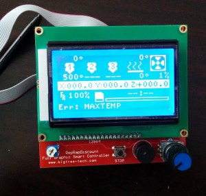
Now you can now control the printer accordingly.
Above screen is for MKS button control screen.
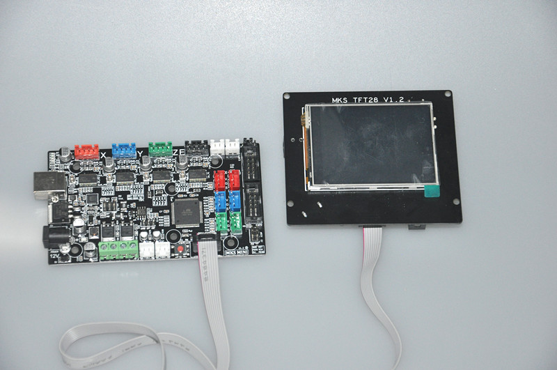
If you want use MKS _TFT touch LCD screen,please read:https://osoyoo.com/2016/07/25/mks-tft-2-8-touch-screen/