Introduction:
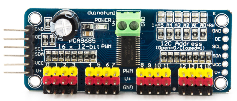
The PCA9685 is a 16-channel I2C-bus controlled LED controller optimized for Red/Green/Blue/Amber (RGBA) color backlighting applications. Each LED output has individual 12-bit resolution (4096 steps) PWM controller with a fixed frequency. The controller operates at a programmable frequency from a typical 24 Hz to 1526 Hz with a duty cycle that is adjustable from 0% to 100% so the LED can be set to output a specific brightness. All outputs are set to the same PWM frequency.
With the PCA9685 as the master chip, the 16-channel 12-bit PWM Servo Driver only needs 2 pins to control 16 servos, thus greatly reducing the occupant I/Os. Moreover, it can be connected to 62 driver boards at most in a cascade way, which means it will be able to control 992 servos in total。
Feature:
1. Contains an I2C-controlled PWM driver with a built-in clock. It means, unlike the TLC5940 family, you do not need to continuously send it signals tying up your microcontroller; it’s completely free running!
2. 5V compliant, which means you can control it from a 3.3V microcontroller and still safely drive up to 6V outputs, which is good when you want to control white or blue LEDs with a 3.4V+ forward voltage
3. Supports using only two pins to control 16 free-running PWM outputs – you can even chain up 62 breakouts to control up to 992 PWM outputs.
4. 3 pin connectors in 4 groups, so you can plug in 16 servos at one time (Servo plugs are slightly wider than 0.1″ so you can only stack 4 adjacent ones on 0.1″-hole female headers.
5. 12-bit resolution for each output – for servos, that means about 4us resolution at an update rate of 60Hz.
6. Size: 62 x 26 mm
Principle:
Based on the above introduction, we can see the module applies the PCA9685 chip as the controller. It can control the output of the 16-channel PWM values. We can manage the PWM frequency and duty cycle to control the servo precisely by programming the controller.
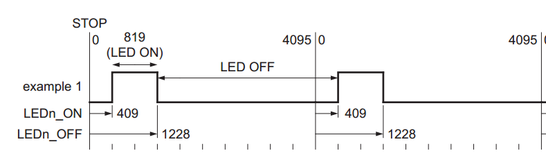
The turn-on time of each LED driver output and the duty cycle of PWM can be controlled independently using the LEDn_ON and LEDn_OFF registers.
If we set the LED_ON time to 409 and LED_OFF time to 1228, the duty cycle of PWM should be:
(1228-409/4096) x 100%= 20%
The servo works like this: The PWM signal captured by the receiving channel is transmitted to the signal demodulation circuit, and a DC offset voltage is generated. Next, this voltage will be compared with the potentiometer’s voltage, and then the voltage drop between them will be input into the motor driving integrated circuit to make the motor rotate clockwise or counter-clockwise. When the rotating speed reaches a certain value, it will drive the potentiometer R0 to spin by the cascaded gear reducer. The motor would not stop rotating until the voltage drop decreases to 0. The servo is controlled by PWM signal, i.e., the changed duty cycle decides where the servo rotates to.
Address the Boards
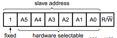
Each board in the chain must be assigned a unique address. This is done with the address soldering pads on the upper right edge of the board. The I2C base address for each board is 0x40. The binary address that you program with the address soldering pads is added to the base I2C address. To program the address offset, use a drop of solder to bridge the corresponding address jumper for each binary ‘1’ in the address.
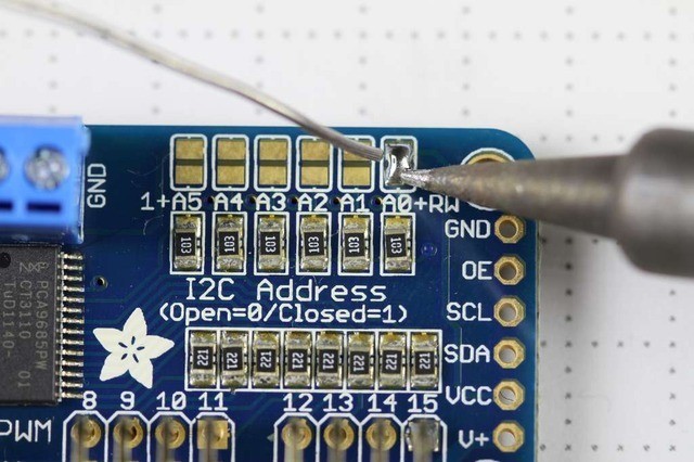
Board 0: Address = 0x40 Offset = binary 00000 (no jumpers required)
Board 1: Address = 0x41 Offset = binary 00001 (bridge A0 as in the photo above)
Board 2: Address = 0x42 Offset = binary 00010 (bridge A1)
Board 3: Address = 0x43 Offset = binary 00011 (bridge A0 & A1)
Board 4: Address = 0x44 Offset = binary 00100 (bridge A2)
State the objects
After assigning the address, you need to state an independent object for each board in the code. See the code below:
/***********************************************************/
#include
#include

Adafruit_PWMServoDriver pwm1 = Adafruit_PWMServoDriver(0x40);
Adafruit_PWMServoDriver pwm2 = Adafruit_PWMServoDriver(0x41);

void setup() {
  Serial.begin(9600);
  Serial.println("16 channel PWM test!");

  pwm1.begin();
  pwm1.setPWMFreq(1600);  // This is the maximum PWM frequency

  pwm2.begin();
  pwm2.setPWMFreq(1600);  // This is the maximum PWM frequency
}
/*************************************************************/
After stating the objects, you can now control the servos via programming as you like!
Examples
Raspberry Pi drive SG90 servo
Resources:
PCA9685 Schematic diagram
PCA9685_datasheet
PWM-Servo-Driver-Library
Python_PCA9685-master


