


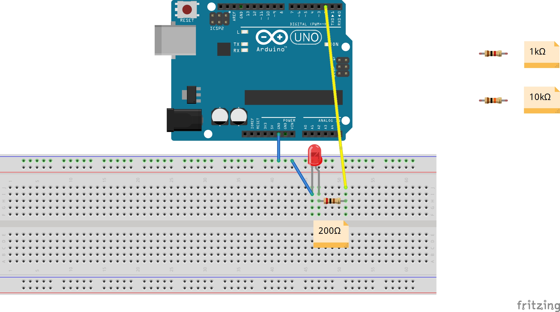
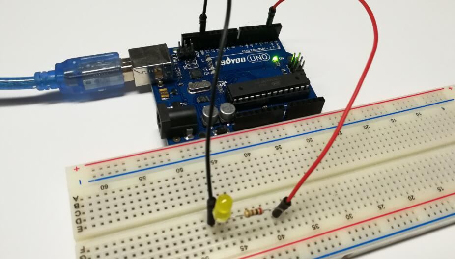
Connect up your stripboard as shown below, using the 200Ω resistor.We attach the LED to an output pin(D2 here) of the Osoyoo Uno.
In this lesson, we will show how to control an LED by using the OSOYOO UNO board. We’ll use graphical programming in this tutorial. If you’re not familiar with it, you can learn about the previous tutorials first.
A breadboard is a rectangular plastic board with a bunch of tiny holes in it. These holes let you easily insert electronic components to prototype (meaning to build and test an early version of) an electronic circuit, like this one with a battery, switch, resistor, and an LED (light-emitting diode).

The connections are not permanent, so it is easy to remove a component if you make a mistake, or just start over and do a new project. This makes breadboards great for beginners who are new to electronics. You can use breadboards to make all sorts of fun electronics projects.
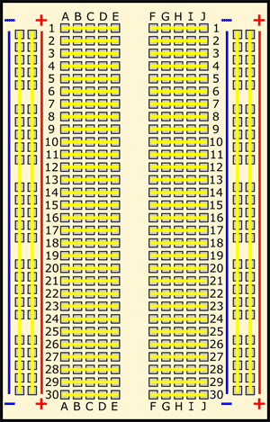
Remember that the inside of the breadboard is made up of sets of five metal clips. This means that each set of five holes forming a half-row (columns A–E or columns F–J) is electrically connected. For example, that means hole A1 is electrically connected to holes B1, C1, D1, and E1. It is not connected to hole A2, because that hole is in a different row, with a separate set of metal clips. It is also not connected to holes F1, G1, H1, I1, or J1, because they are on the other “half” of the breadboard—the clips are not connected across the gap in the middle (to learn about the gap in the middle of the breadboard, see the Advanced section). Unlike all the main breadboard rows, which are connected in sets of five holes, the buses typically run the entire length of the breadboard (but there are some exceptions). This image shows which holes are electrically connected in a typical half-sized breadboard, highlighted in yellow lines.
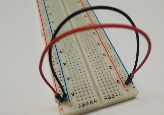
Buses on opposite sides of the breadboard are not connected to each other. Typically, to make power and ground available on both sides of the breadboard, you would connect the buses with jumper wires, like this. Make sure to connect positive to positive and negative to negative (see the section on buses if you need a reminder about which color is which).If you want to get more info about the breadboard,please check this link.
Notice:
When you start to put components on your breadboard, avoid adding, removing, or changing components on a breadboard whenever the board is powered. You risk shocking yourself and damaging your components.
LEDs (that’s “ell-ee-dees”) are a particular type of diode that convert electrical energy into light. In fact, LED stands for “Light Emitting Diode.” (It does what it says on the tin!) And this is reflected in the similarity between the diode and LED schematic symbols:
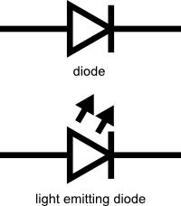
In short, LEDs are like tiny lightbulbs. However, LEDs require a lot less power to light up by comparison. They’re also more energy efficient, so they don’t tend to get hot like conventional lightbulbs do (unless you’re really pumping power into them). This makes them ideal for mobile devices and other low-power applications.
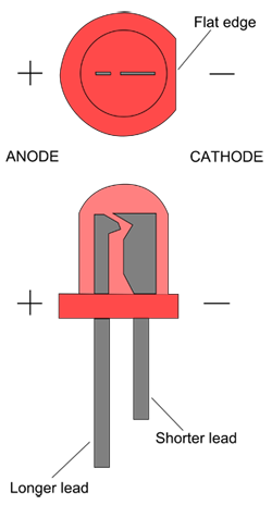
LEDs have a positive side (called the anode) and a negative side (called the cathode). The metal lead for the anode is longer than the lead for the cathode. The cathode side also usually has a flat edge on the plastic part of the LED.More info about the LED please check this link.
Resistors are electronic components which have a specific, never-changing electrical resistance. The resistor’s resistance limits the flow of electrons through a circuit.
They are passive components, meaning they only consume power (and can’t generate it). Resistors are usually added to circuits where they complement active components like op-amps, microcontrollers, and other integrated circuits. Commonly resistors are used to limit current, divide voltages, and pull-up I/O lines.We are going to use this to control how much electricity flows through the LED and therefore how brightly it shines.
The electrical resistance of a resistor is measured in ohms. The symbol for an ohm is the greek capital-omega: Ω. The (somewhat roundabout) definition of 1Ω is the resistance between two points where 1 volt (1V) of applied potential energy will push 1 ampere (1A) of current.
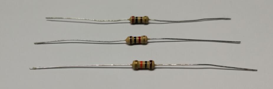
In this lesson, we are going to use three different values of resistor, 200Ω, 1kΩ and 10kΩ. These resistors all look the same, except that they have different colored stripes on them. These stripes tell you the value of the resistor.
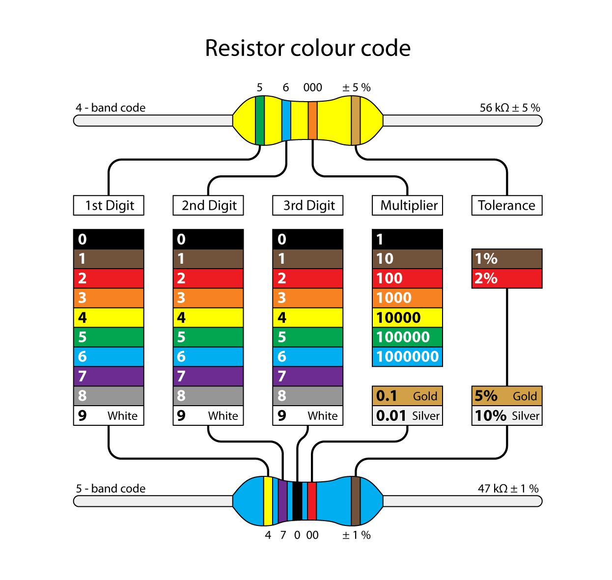
The resistor color code works like this, for resistors like this with three colored stripes and then a gold stripe at one end.
Unlike LEDs, resistors do not have a positive and negative lead. They can be connected either way around.More info about resistor please check this link.
Connect the Arduino board to your computer using the USB cable. The green power LED (labelled PWR) should go on.
This lesson is very similar to the last one, as long as the pin number is changed from 13 to 9.
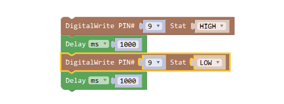
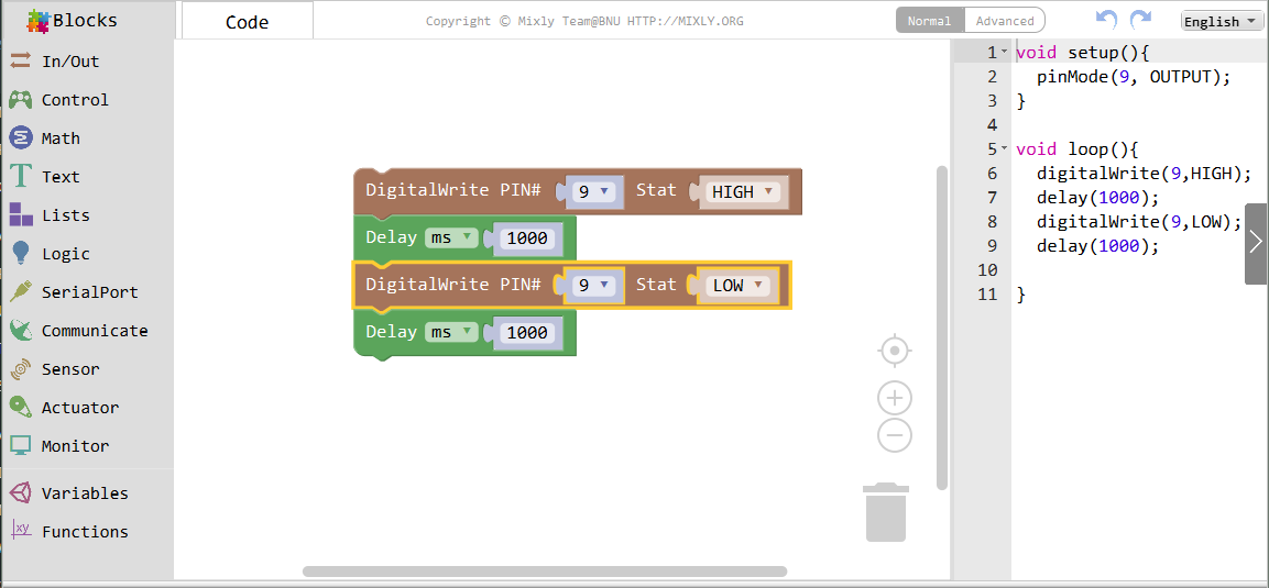
This program will give a high or low level to the LED connected pin 9 to turn it on and off. After programming, you can click the “<" button to check the corresponding code on the right bar.
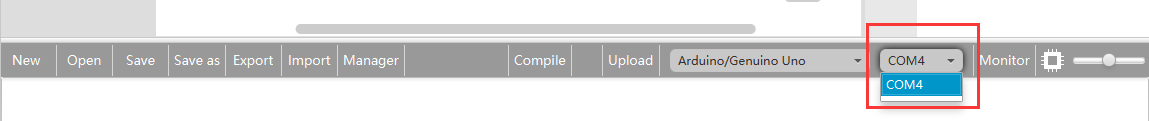
Click Save aftogramming is done. Select the board type and serial port before uploading. For instause a Uno board, just select Arduino/Genuino Uno: if you use a Mega2560, select Arduino/Genuino Mega or Mega2560.

Select the serial device of the Arduino board from the COM menu. This is likely to be COM3 or higher (COM1 and COM2 are usually reserved for hardware serial ports). To find out, you can disconnect your Arduino board and re-open the menu; the entry that disappears should be the Arduino board. Reconnect the board and select that serial port.
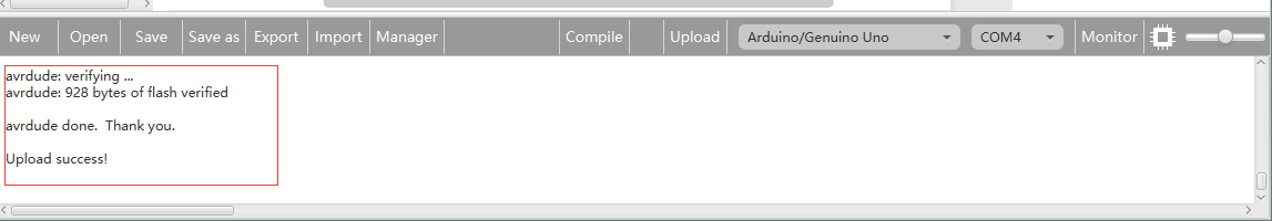
Next,upload the code. If the uploading fails, check and correct the code according to the prompts
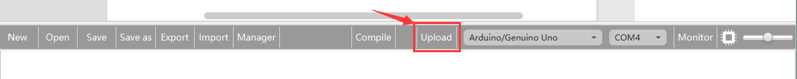
Finally, the staus will change to ‘Upload success!’.
A few seconds after the upload finishes, you should see the pin 2 LED on the breadboard start to blink as below:
With the 200 Ω resistor in place, the LED is quite bright.
Now we swap out the 200 Ω resistor for the 1k Ω resistor, then the LED appear a little dimmer:
Finally, with the 10 kΩ resistor in place, the LED is quite faint:
DownLoad Url osoyoo.com