Objective:
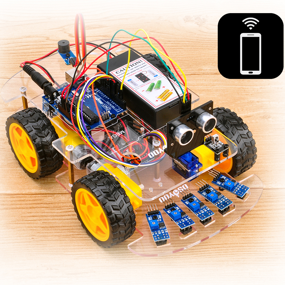
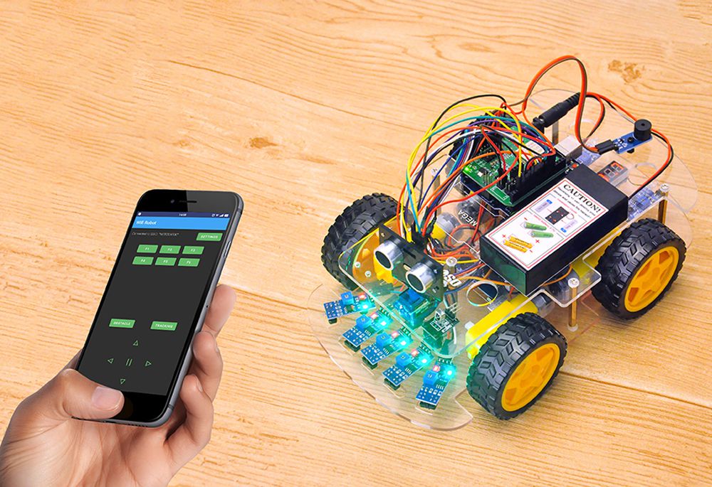
In this project we will connect Robot Car to WIFI and Use an APP to control the car through Internet. This is a typical Internet of Things(IoT) Application.
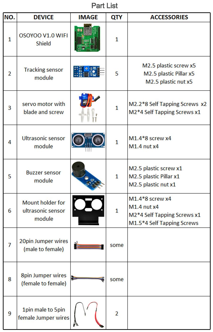
Step 1: Install the smart car basic frame work as per Smart Car Lesson 1 . If you have already completed installation in Lesson 1 , please remove all wires on Osoyoo Uno R3 board
Step 2: Insert to Osoyoo WIFI Shield onto your UNO board
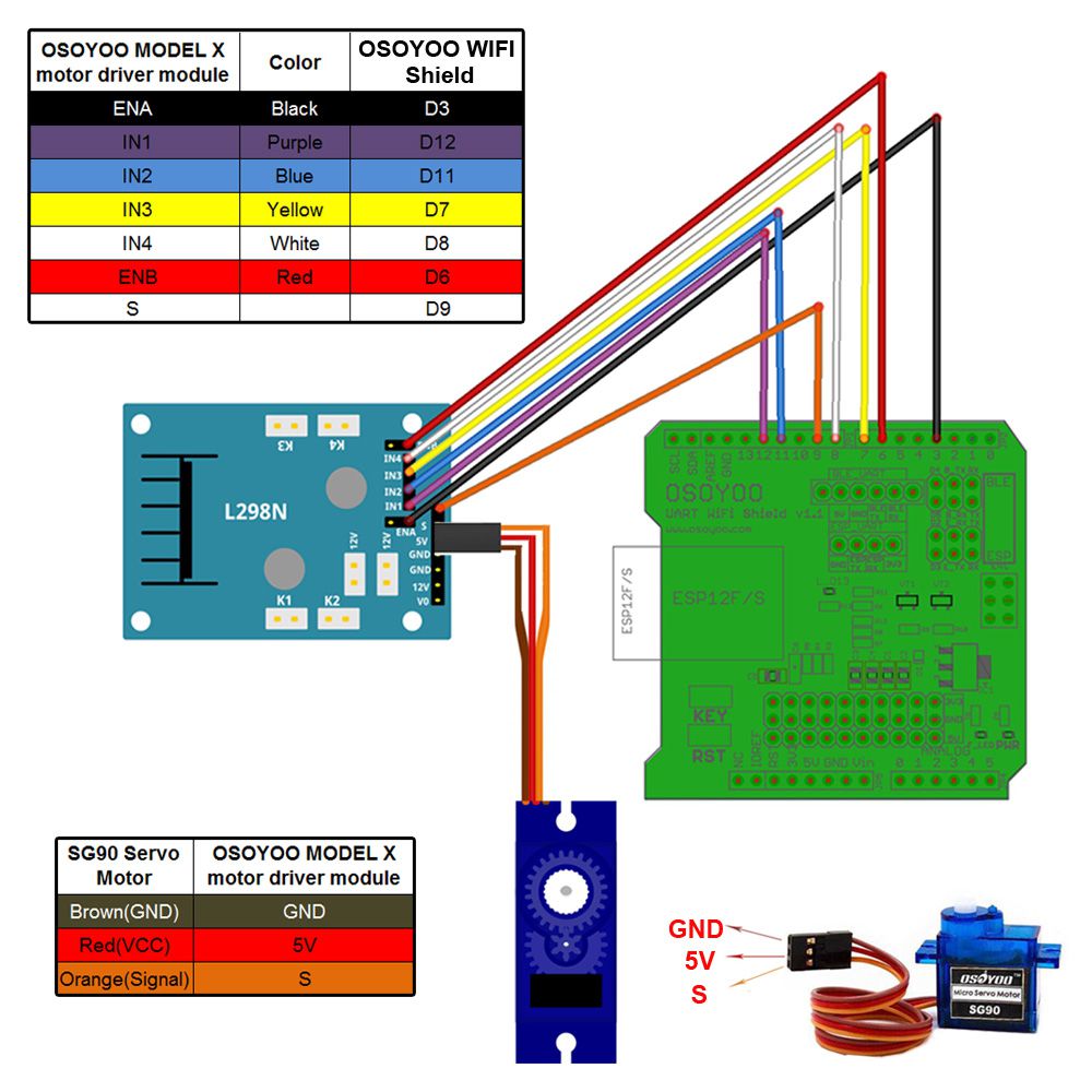
Step 3: Connect SG90 servo motor, OSOYOO MODEL X motor driver module and OSOYOO Wifi Shield as following graph:
Step 4: Connect 5pcs tracking sensor modules with OSOYOO wifi shield as below connection diagram (if you remove the wires on tracking sensor modules, you need to remove the screws on copper pillars)
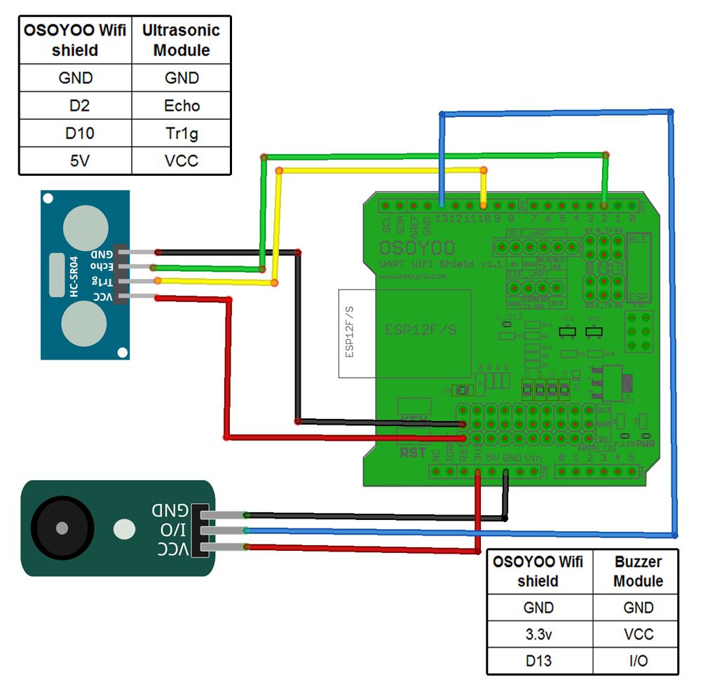
Step 5: Connect ultrasonic module, buzzer module with OSOYOO WIFI shield as below connection diagram
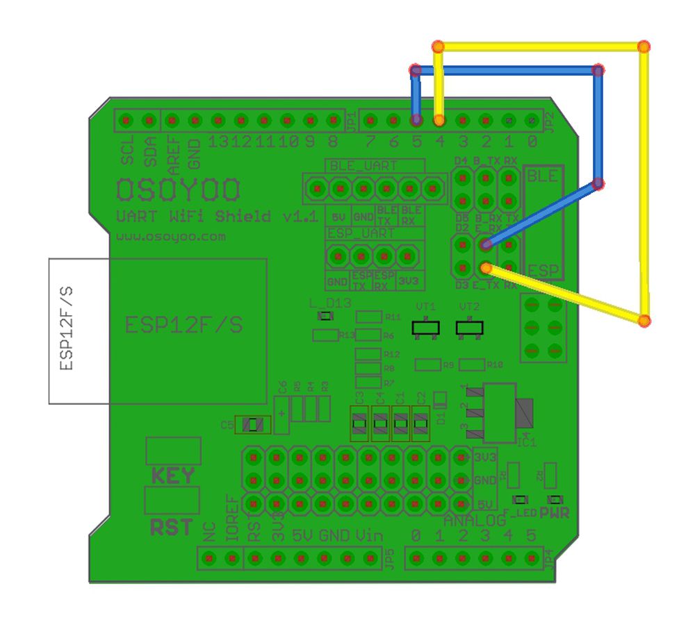
Step 6: Connect E_TX (Esp8266 TX) pin to Arduino D4(UNO soft serial RX) and E_RX(ESP8266_RX) pin to D5(UNO software serial TX) as per following picture
Step 7:Fix the screws on copper pillars to connect upper chassis to lower chassis (if don’t remove screws on copper pillars, please skip this step)
Step 8: After connected above wires, download a test sketch file from L6 test code. After uploading this file to Arduino and turning on your car, it should move forward ,backward, left turn , right turn and then stop. If the car does not move in above mentioned scenario, please check your wiring
search “Osoyoo WIFI Robot APP” in
Google Play or Apple Store
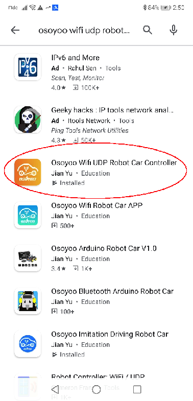
Step 1) Download OSOYOO WIFI UDP Robot Car control APP
In Google Play or Apple Store, please search key words “OSOYOO WIFI UDP Robot Car”, you will find an orange icon APP as following:
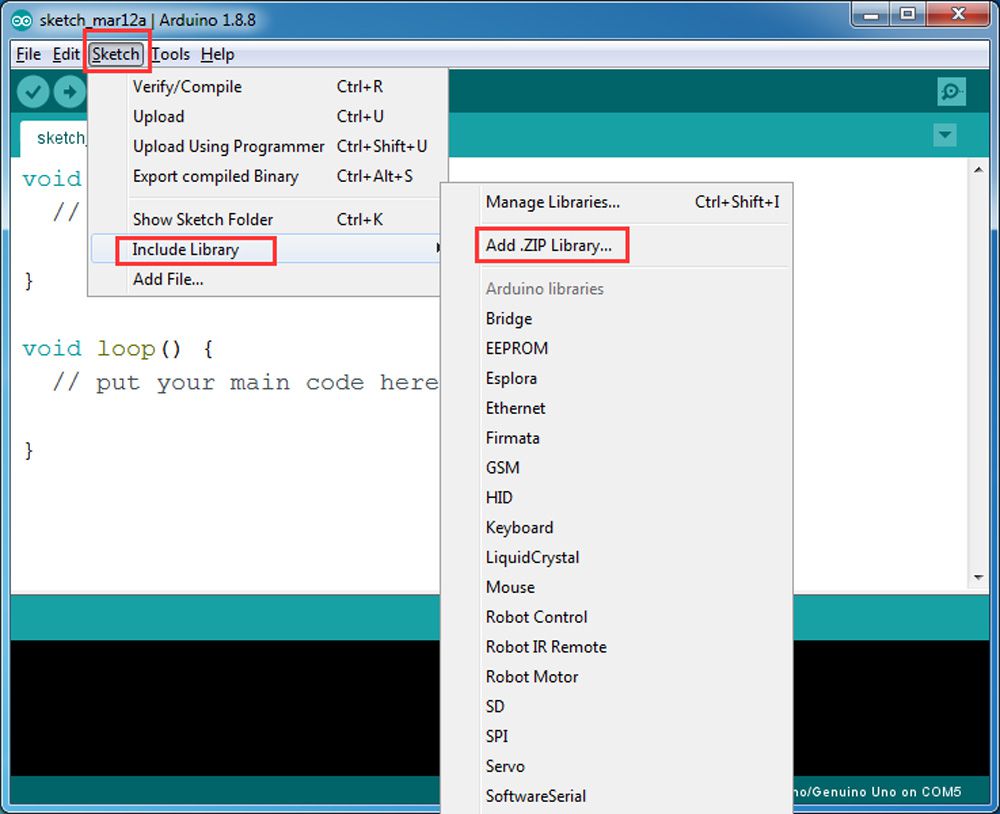
Step 2) Please download the library zip file from WiFiEsp-master .Open Arduino IDE ->click Sketch ->Include Library ->Add .ZIP library , then load above zip file into Arduino.
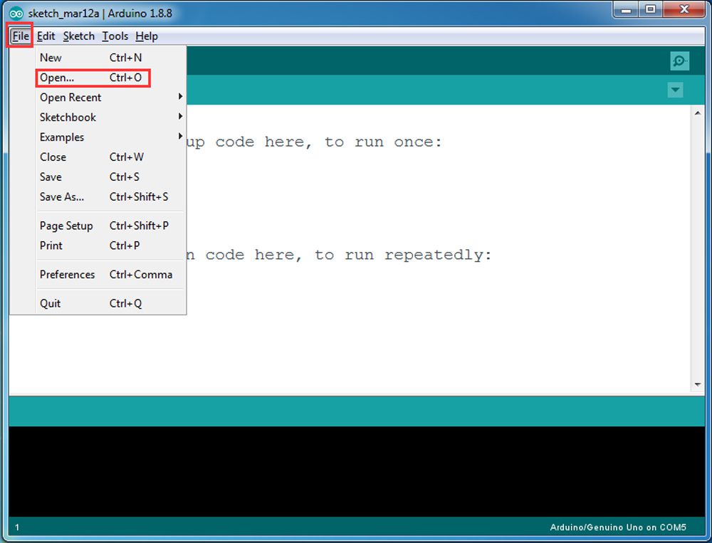
Step 3) Arduino Sketch code Installation:
Download: https://osoyoo.com/driver/arduino-udp/v2car-lesson6.zip
Osoyoo V2 Robot Car can work in two WIFI modes: STA mode and AP mode. The Arduino sketches for these two modes are different. Let’s explain these two modes one by one
A)STA mode In STA mode, V2 Robot Car will be a client device of your LAN router. You need save the SSID name and password of your LAN router in Arduino sketch.
Once the sketch is running, your router DHCP service will assign an IP address to your robot car and your APP will use this IP address to access your car.
1) Go to v2smartcar-lesson6C sub folder, Run STA mode sketch code file v2smartcar-lesson6C.ino
2) You need change the code Line 96 and Line 98 :
char ssid[] = “YOUR_ROUTER_SSID”; // replace this with your router wifi SSID
char pass[] = “YOUR_ROUTER_WIFI_PASSWORD”; // replace with your wifi password
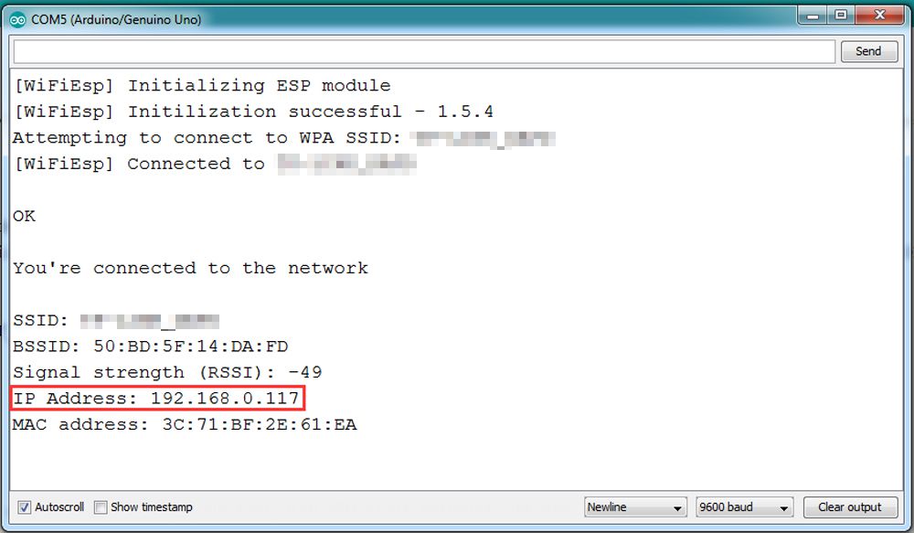
3) Upload the sketch to Arduino. Finally, click the Serial monitor window in upper right corner of Arduino IDE, you will see following result:
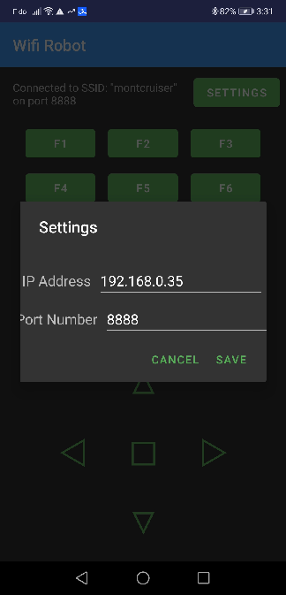
4) In this mode, your will see an IP address which is our LAN IP address assigned by my router. Please write down this IP address and click Setting to set up robot IP address and set this IP address to your APP Setting section (no need change default port 8888 in APP).
Now your Robot car is connected to your LAN, you can use Mobile phone under same LAN to control the robot car. If your APP is in WAN, you need to go to your Router Control Panel, forward Port 80 to Robot car LAN IP address, then you can use Router IP to control the car. This feature makes our robot car A REAL INTERNET OF THING device
B)AP mode
Sometimes we do not have a LAN or WIFI Router. In order to control the car, we need to use AP mode.
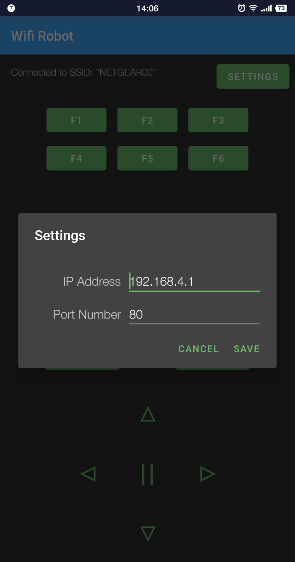
When working in AP mode, our robot car itself will become a WIFI Hot Spot. Our cell phone can connect to Robot Car as its wifi client. The IP address of Robot is fixed as 192.168.4.1 and It is not connected to WAN.
1)Go to v2smartcar-lesson6D sub folder, Run AP mode sketch file v2smartcar-lesson6D.ino
2) Open your Arduino Serial monitor, and you will see a similar result as STA mode. A new WIFI SSID “osoyoo_robot” with IP address 192.168.4.1 will show up in the window. This means your Robot car has a WIFI Hot Spot name “osoyoo_robot” , its IP address is 192.168.4.1
3) Connect your cell phone to “osoyoo_robot” wifi hot_spot, and set IP address as “192.168.4.1” to your APP Setting section, use Default Port 8888
Now your Robot car become a WIFI Hot Spot, you can use Mobile phone control the robot car.
Final Testing:
Trun on the car. Now click Setting to set up robot IP address.
In STA mode, you need connect cell phone to the same LAN ssid of your robot car and set IP address same as the Robot IP showed in Arduino Serial Monitor.
In AP mode , you need contact your cell phone to “osoyoo_robot” wifi hot_spot and set IP address as 192.168.4.1
you can click the < > ^ v direction keys to make the car move. Use || pause key to stop the car movement.
If you click Obstacle key, the car will do obstacle avoidance auto driving similar to Lesson 5
If you click Tracking key, the car will do link tracking auto driving similar to lesson 4
Note: F1~F6 are further development functions in the future.
FAQ about the WIFI UDP APP and sketch Code: Q 1)What happened when you press buttons in OSOYOO WiFi UDP Robot Car APP ? A: When you press a button of the APP, APP will send a single-letter message through UDP protocol to target device (in this example, our Arduino Wifi Shield)
Button
UDP message
F1
F
F2
G
F3
H
F4
I
F5
J
F6
K
▲
A
▼
B
►
R
◄
L
🢐
E
obstacle
O
tracking
T
Q2)How does Arduino handle the UDP command?
Line 315 to line 327 in v2smartcar-lesson6c.ino file are the codes which react to Cell phone command. For example, when ▲ is pressed, according to Q1 table, a letter “A” command was sent from Cell phone to Arduino. Line 319 case ‘A’ …. statement will make the car make car moving forward.
      char c=packetBuffer[0];
            switch (c)    //serial control instructions
            {

               case 'A':Drive_Status=MANUAL_DRIVE; Drive_Num=GO_ADVANCE;  WorkMode="GO_ADVANCE";break;
               case 'L':Drive_Status=MANUAL_DRIVE; Drive_Num=GO_LEFT; WorkMode="GO_LEFT";break;
               case 'R':Drive_Status=MANUAL_DRIVE; Drive_Num=GO_RIGHT;WorkMode="GO_RIGHT";break;
               case 'B':Drive_Status=MANUAL_DRIVE; Drive_Num=GO_BACK;WorkMode="GO_BACK";break;
               case 'E':Drive_Status=MANUAL_DRIVE; Drive_Num=STOP_STOP;WorkMode="STOP_STOP";break;
               case 'O':Drive_Status=AUTO_DRIVE_UO;Serial.println("go OBSTACLE");WorkMode="OBSTACLE";break;
               case 'T':Drive_Status=AUTO_DRIVE_LF; Serial.println("GO line follow...");WorkMode="line follow";break;
               default:break;
              } //END OF ACTION SWITCH


Although no obstacle was detected, the car jerked in short drives forward. Can I extend the length of this driving without obstacle detection?