


In this lesson, we will teach you how to install the OSOYOO V2.0 Raspberry Pi Robot Car basic frame work.
And we will use C++ to make a simple program to make two motors in K1 and K3 move forward for 2 seconds then move backwards for two seconds. You will learn how C++ sends digital data to GPIO pins, how to send PWM (analog) signal to PCA9685 module.
If you are interested in Python programming, we have same project in Python language, here is the link:
https://osoyoo.com/2020/08/01/how-to-use-osoyoo-model-pi-l298n-motor-driver-board-in-raspberry-pi-robot-car/

OSOYOO Car chassis with two motors x1
Raspberry pi 4 or 3 or 3B board x1 (NOT Included)
OSOYOO Model Pi motor driver board x1
OSOYOO PCA9685 compatible module x1
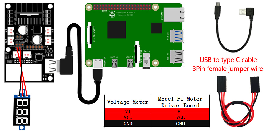
OSOYOO Voltage Meter x1
18650 Battery box x1
18650 batteries x2
Some jumper wires

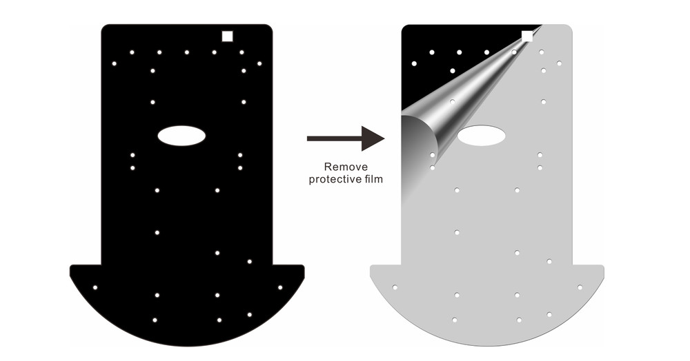
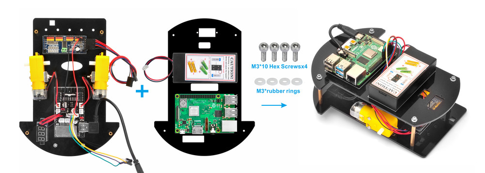
1) Remove the protective film on upper and low car chassis (Each car chassis has one protective film).
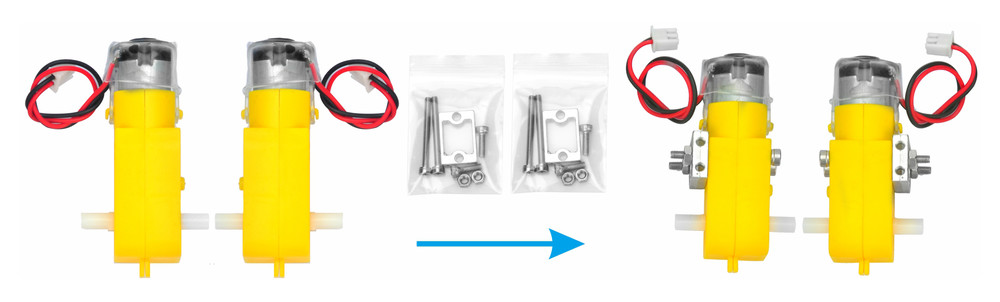
2) Install 4 motors with Metal Motor Holders as follows.
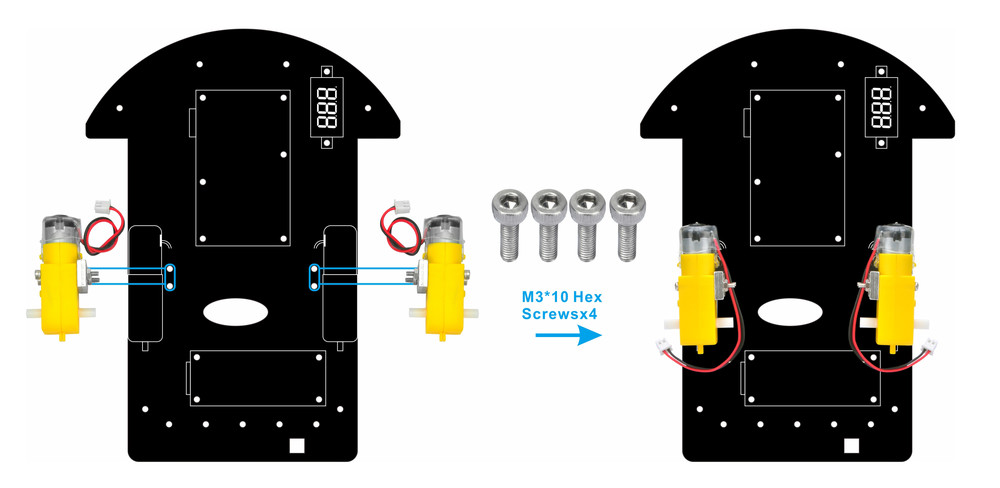
3) Install 4 motors on lower car chassis with screw M3*10 (screws in metal motor holder package).
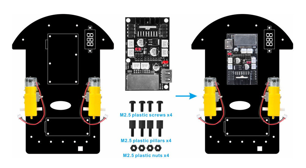
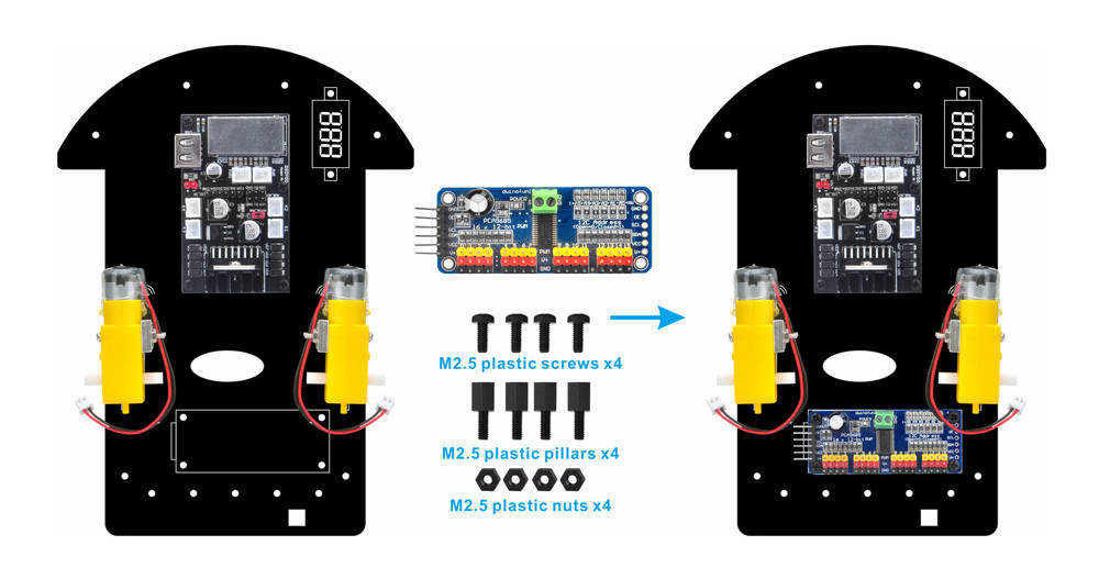
4) Install OSOYOO MODEL Pi motor driver module to car low chassis with 4pcs M2.5 plastic screws, plastic pillars and plastic nuts. (Please make sure you install the OSOYOO MODEL Pi motor driver module in correct direction.)
5) Install PCA9685 compatible board on lowcar chassis with 2pcs M2.5 plastic screws, plastic pillars and plastic nuts
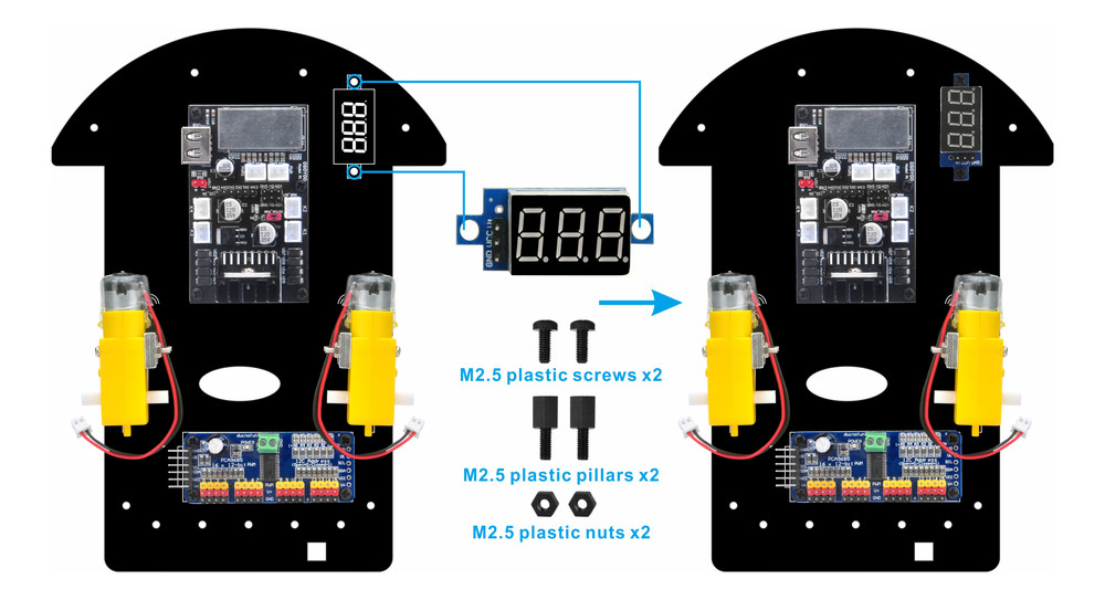
6) Install voltage meter on low car chassis with 2pcs M2.5 plastic screws, plastic pillars and plastic nuts.
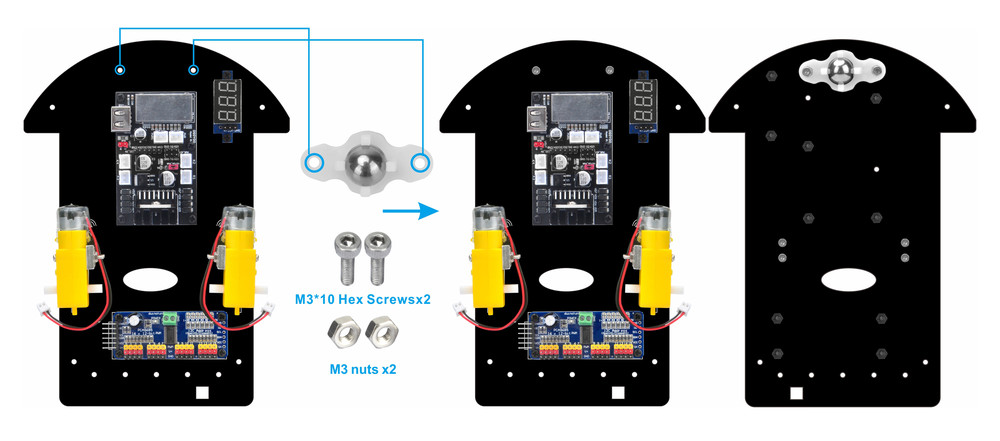
7) Install universal wheel on low car chassis with 2pcs M3x10 hex screws and M3 nuts.
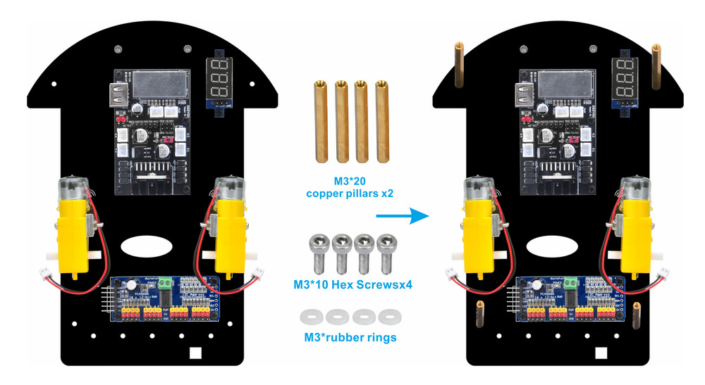
8) Install 4pcs copper pillars on low car chassis with 4pcs M3x20 hex screws and M3 nuts.
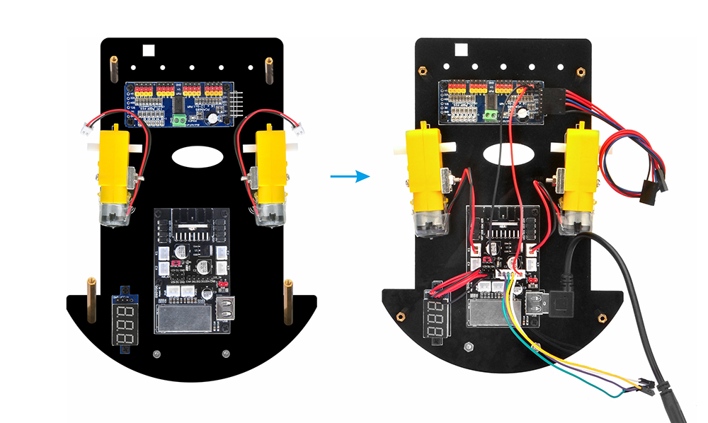
9)You need to plug 2pin 20cm female to female cable and 3pin 20cm female to female cable on PCA9685 compatible board. Use 3pin 15cm female to female cable to connect voltage meter to model pi motor driver board.
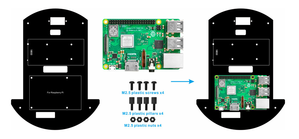
10) Install raspberry pi board on low car chassis with 4pcs M2.5 plastic screws, plastic pillars and plastic nuts.
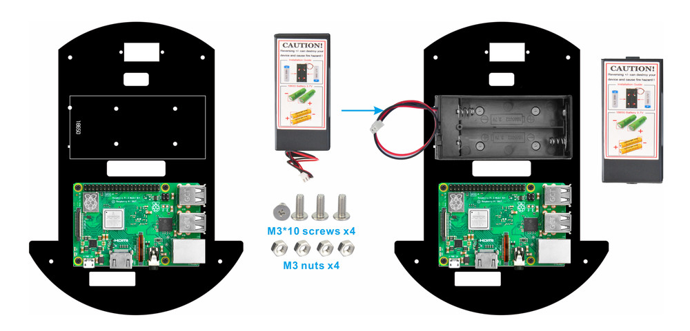
11) Install 18650 battery box on upper car chassis with 4pcs M3x10 screws and nuts.
12)Connect battery box connector to model pi board as per following graph.
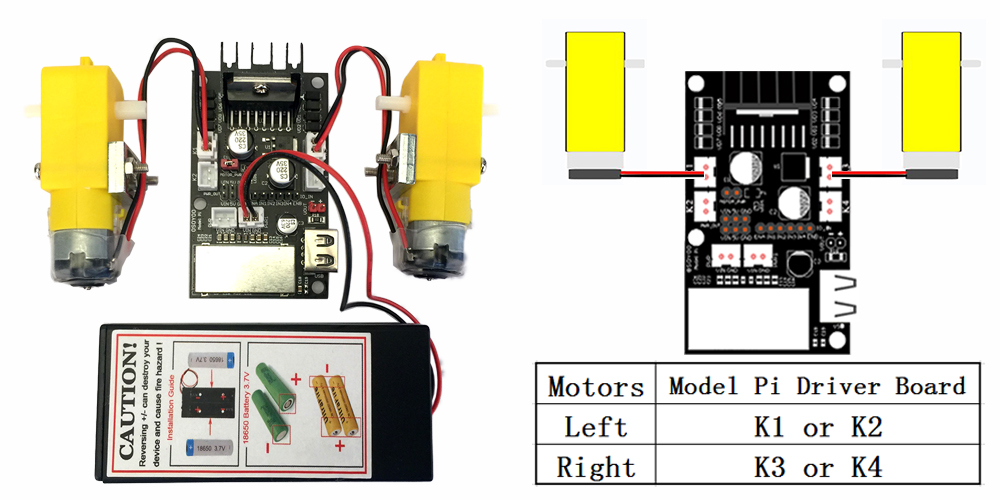
ENA connect to PCA9685 PWM0,ENB connect PCA9685 PWM1. K1 and K2 are same, K3 and K4 are same, see following pictures:
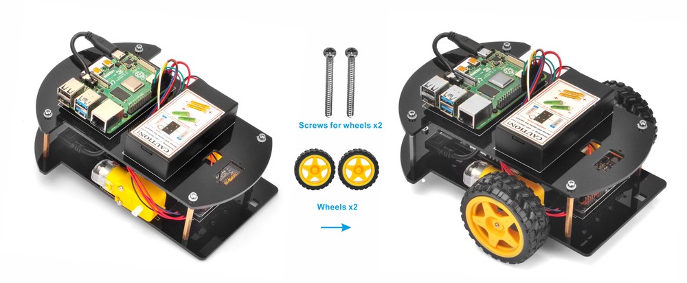
12) Connect upper chassis to lower chassis with 4pcs M3*10 hex screws and 4pcs M3 rubber rings, then install 2 wheels onto the motors.

Circuit Connection:
The most important part in this project is OSOYOO Model-Pi motor drive board- an improved L298N module which can power motor and Raspberry Pi at the same time.
OSOYOO Model-Pi L298N board is perfect motor driver board for Raspberry Pi portable applications such as robots, RC cars , drones , mini weather station etc.
This board supports all the features of L298N DC motor driver, in addition, it also has a USB 5V output port which can provide stable voltage to Raspberry Pi board.
I/O pins fully compatible with L298N including EnableA/IN1/IN2/IN3/IN4/EnableB. Two Channels of PWM output and to control left and right wheels. Each Channel has two output sockets (K1/K2 for right side wheels and K3/K4 for left side wheels)
There are 6 input-signal pins ENA,IN1,IN2,IN3,IN4,ENB and two pairs of output socket (K1/K2, K3/4) which connect to left and right motors.
Input power source can be 7.5v-24v batteries (we suggest using 2pcs tandem 18650 batteries etc, or 6pcs AAA Tandem AAA batteries, or , 2pcs Parallel 9V batteries for robot project).
USB port gives stable 5V/2.4A output.
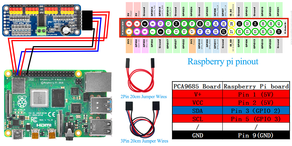
Picture 1:Connect PCA9685 compatible board to raspberry pi board as per picture 1.
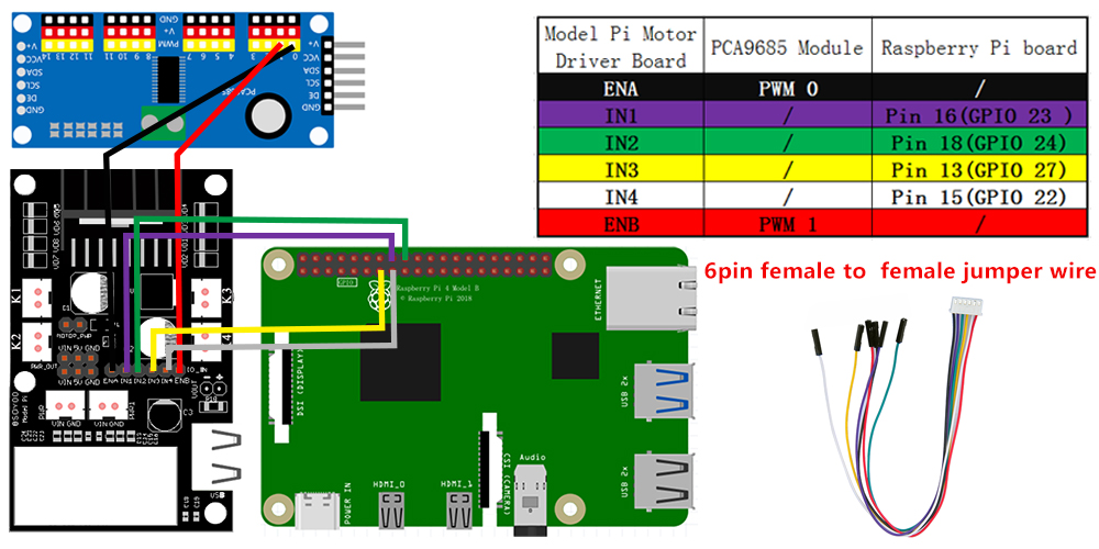
Picture 2:Connect Model Pi six control pins to the Raspberry Pi GPIO pins and PCA9685 PCA9685 Compatible module as picture 2.
Picture 3: Model Pi connection map to Raspberry Pi board as per picture 3.
ENA gets PWM signal (analog current signal) from raspberry pi or Arduino. If ENA current is high, K1,K2 will have higher rotation speed.
ENB gets PWM signal (analog current signal) from raspberry pi or Arduino. If ENB current is high, K3,K4 will have higher rotation speed.
IN1,IN2 digital input pins determine the rotation direction of K1,K2 motor. If IN1=HIGH(1), IN2= LOW (0),motor in K1 or K2 moves forward. If IN1=LOW, IN2= HIGH, K1 or K2 motor moves backward. If IN1,IN2 has same voltage , K1/K2 motor does not move.
IN3,IN4 digital input pins determine the rotation direction of K3,K4 motor. If IN3=HIGH(1), IN4= LOW (0),motor in K3 or K4 moves forward. If IN3=LOW, IN4= HIGH, K3 or K4 motor moves backward. If IN3,IN4 has same voltage , K3/K4 motor does not move.

Software Preparation:
OS: Raspbian (Use OS Raspbian 2020-05-27 in the subsequent tutorials )
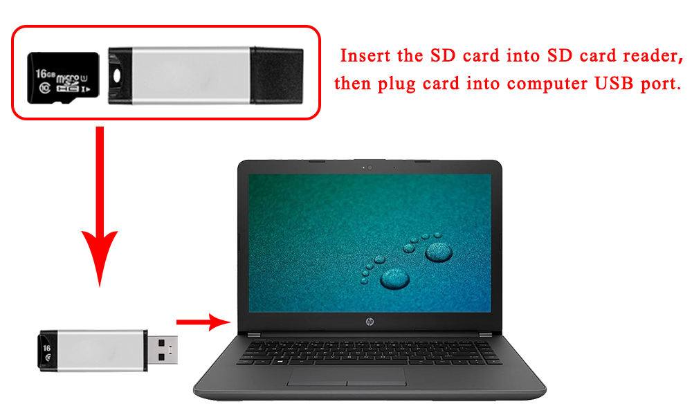
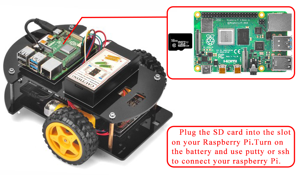
Step 1:Before connect to Raspberry Pi, you need to install Raspbian Operation System(OS) onto SD card(skip this step if your SD card has pre-installed OS Raspbian Image).
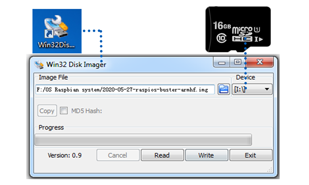
You can select the latest version of raspbian system on the official website: https://downloads.raspberrypi.org/raspbian/images/.Write the image via Win32DiskImager utility into your microSD/TF card(minimum 16G) via SD card reader.
Step 2: Connect Wifi
Firstly, Connect Raspberry Pi to your HDMI monitor or TV. Put a keyboard and mouse into Raspberry Pi USB ports. Insert SD card into the slot on your Raspberry Pi. 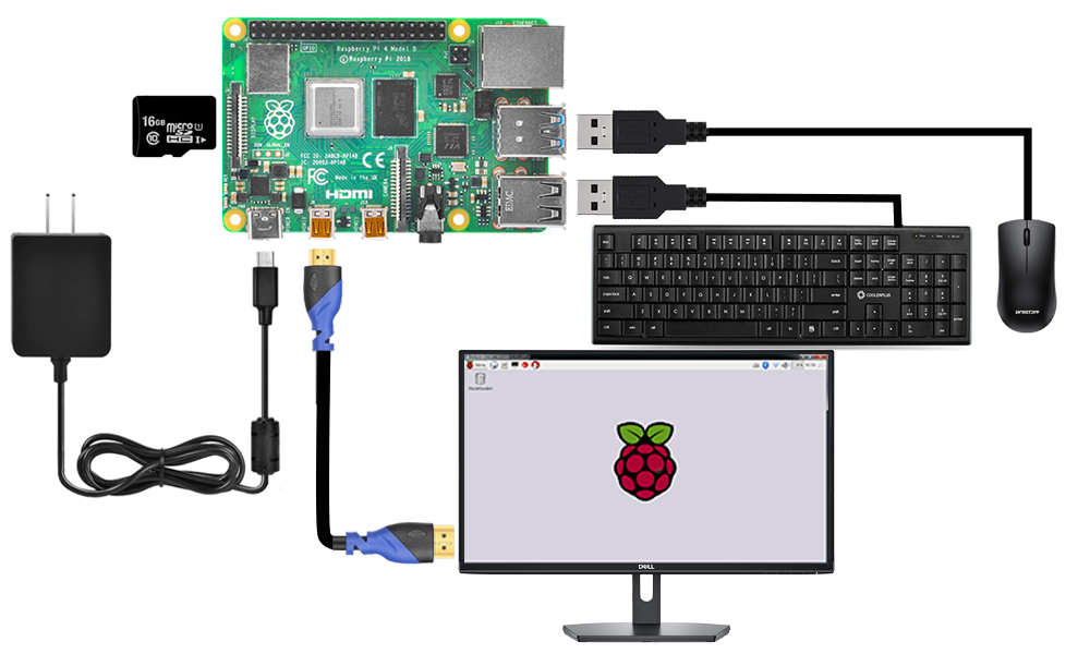
Click on the wireless icon top right on desktop, should give a list of access points, select your wifi ssid and connect it. Once your Pi is connect to Wifi, you can hover your mouse to the wifi icon to see the your IP address.Or your can type hostname -I command in terminal. Your local ip address will look like
192.168.50.182 fd00:bc4d:fba4:fea2:c4a1:a409:4853:917d
……
in above example, 192.168.50.182 is your Raspberry Pi IP Address, you will use it in Step 3) ssh command.
Step 2: Enable SSH
press Ctrl-T and open command terminal. Then type :
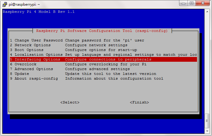
sudo raspi-config
You will go to configuration menu, select Interface Options ->SSH -> Yes ->OK ->Finish
Now reboot your Raspberry Pi, you can use Putty or SSH to remotely access raspberry pi.
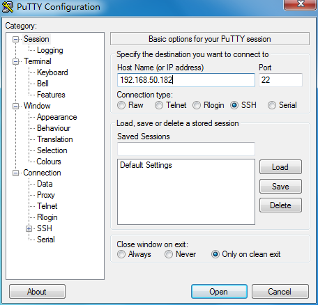
Step 3: use putty or ssh to connect your raspberry Pi by typing
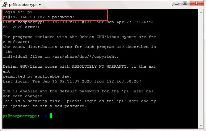
ssh pi@192.168.50.182 (this example IP address is from STEP 1)
Admin: pi
Password: raspberry
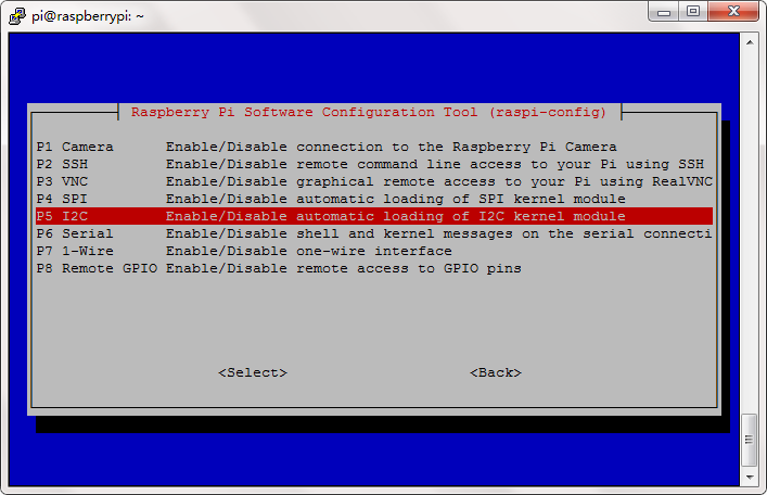
Step 4: Enable I2C
If you have not enable I2C, please run following command to enable I2C.
sudo raspi-config
Then select Interfacing Options->I2C->Yes->Ok->Finish
Step 5:) Load IIC Modules(if you have done, please skip)
sudo nano /etc/modules
open /etc/modules file,Add i2c-bcm2708 into devices and make these two lines as below:
i2c-bcm2708
i2c-dev
reboot your pi to enable the setting
Step 6: Type following command to download the PCA9685 library.
wget http://osoyoo.com/driver/p3-car/pca9685.tar.gz
tar -zxvf pca9685.tar.gz
You will see a new directory PCA9685 , PCA9685 driver code files are in this folder:
Step 6: Type following command to download the lesson1 C code file.
wget http://osoyoo.com/driver/p3-car/lesson1.c
Step 7: Compile source code into executable file
C is a compiled language which means its source code must be compiled into an executable file. This is quite different from Python which is an interpreted language(You just type Python3 your_source_code_file, then you can run the python program).
Before compiling the C code, you need to install wiringPi library by following command:
sudo apt-get install wiringpi
Now we can compile our sample C code by typing the command:
gcc -o lesson1 lesson1.c pca9685/pca9685.c -lwiringPi
Above command will generate an executable file lesson1 , now we can run the program by typing following command:
./lesson1
After running above program , your car will move forward for 1 seconds and then move backward for 1 seconds, and turn left for 1seconds and turn right for1 seconds then stop.


