
In Lesson 1 and lesson 2 , we use Basic board and OSOYOO ESP8266 WIFI module to make some simple web server and transfer data through HTTP protocol.
In this lesson, we will teach you to use a very simple and power protocol called UDP which is commonly used for Email service and control signal. We will use a cell phone APP to turn On/Off an LED in Basic board remotely through UDP protocol.
UDP is a simple and powerful protocol which are often used in email and one-way data transfer applications. As Basic board board has very limited memory, UDP protocol usually has better performance than other IoT protocols such as HTTP and MQTT.

OSOYOO Basic board x 1
OSOYOO ESP8266 WIFI Shield x 1
LED x 1
200 ohm resistor x 1

Circuit Connection:
| OSOYOO WIFI Module |
Basic board |
| E_RX |
D5 |
| E_TX |
D4 |
| GND |
GND |
| VCC |
5V |
| LED |
Basic board |
| Long Pin |
D13 |
| Short Pin |
GND(thru 200 omh resistor) |
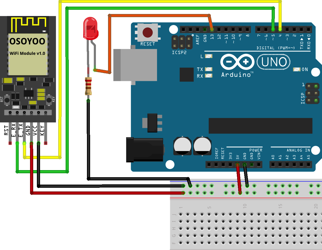
Download above Fritzing circuit diagram file from following link:
https://osoyoo.com/driver/osoyoo-esp8266-module/lesson3/osoyoo-wifi-module-lesson3.fzz

Step 1) If you haven’t install IDE and WIFI ESP Master Library, please read lesson 1 and install the library.
Step 2)Download the sketch file from : https://osoyoo.com/driver/osoyoo-esp8266-module/lesson3/esp8266-lesson3.zip
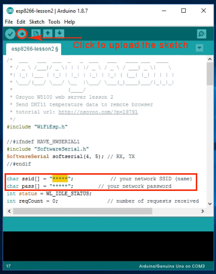
Unzip the download file and enter the folder esp8266-lesson3, double click to open esp8266-lesson3.ino file.
In the sketch, find following lines:
char ssid[] = "******"; // your network SSID (name)
char pass[] = "******"; // your network password
please replace the ****** with your correct wifi SSID and password, otherwise your project can
 not connect to Internet.
After changing the WIFI password, please upload the code to Basic board. Open serial monitor, you will see:
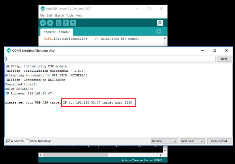
In above example, 192.168.50.47 is your Basic board IP address. We will use this IP address to send UDP command.

Step 3) Install UDP send Mobile APP
You can use any UDP send APP to run this lesson. In this lesson, we use OSOYOO WIFI UDP Robot Car APP to make the test.
In Google Play or Apple Store, please search key words “OSOYOO WIFI UDP Robot Car”, you will find a yellow icon APP .
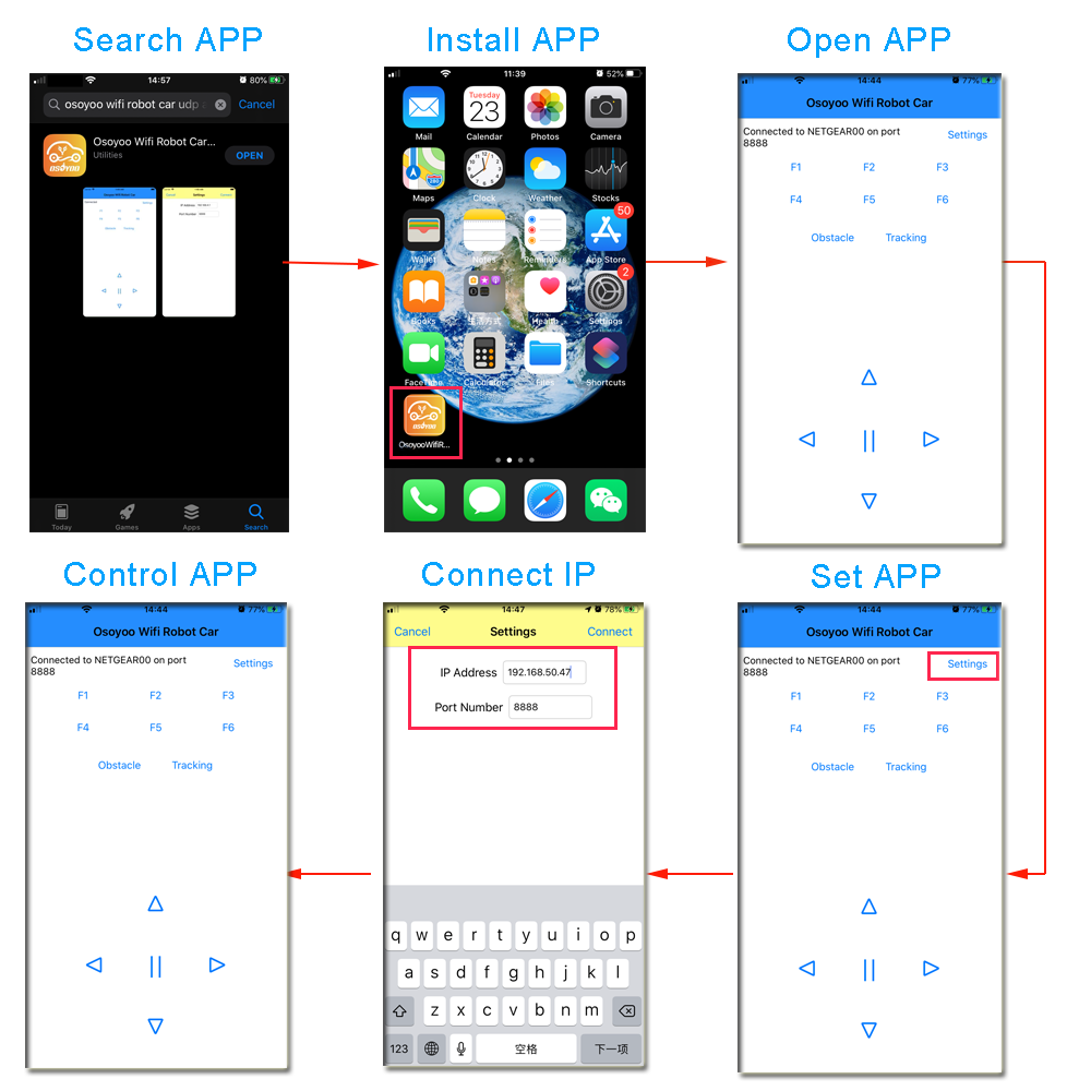
In APP UI screen, click F1 button, your LED will be turn on , then click F2 button, your LED will be turn off.
How does this work?
When you click F1 button, our cell phone APP actually send “F” letter through UDP protocol to your Basic board.
When you click F2 button, our APP send “G” letter through UDP protocol to your Basic board.
If you don’t use OSOYOO robot car UDP APP, you can use any other UDP sending software to send an “F” or “G” UDP packet to your Basic board IP address port 8888. The result will be the same.
Following Basic board code handle the F1 and F2 command:
      switch (c)    //serial control instructions
      {

        case 'F': digitalWrite(ledPin, HIGH) ;break; //TURN ON LED
        case 'G':digitalWrite(ledPin, LOW) ;break; //TURN OFF LED

        default:break;
      }
You can see :
when Arduino receives “F” UDP message, then it gives ledPin a HIGH digital signal to turn on the LED.
when Arduino receives “G” UDP message, then it gives ledPin a LOW digital signal to turn off the LED.


bbbb