In this lesson, we will be imitating an automatic light system. When the photoresistor sensor detects that the natural environment light is dark, the computer will turn on the man-made light (LED). When the natural environment is bright, the computer will turn off the LED.
Through this project, we will learn how to use variable blocks and analog input blocks.
Raspberry Pi Pico board and microUSB cable
A computer to run Thonny Python IDE
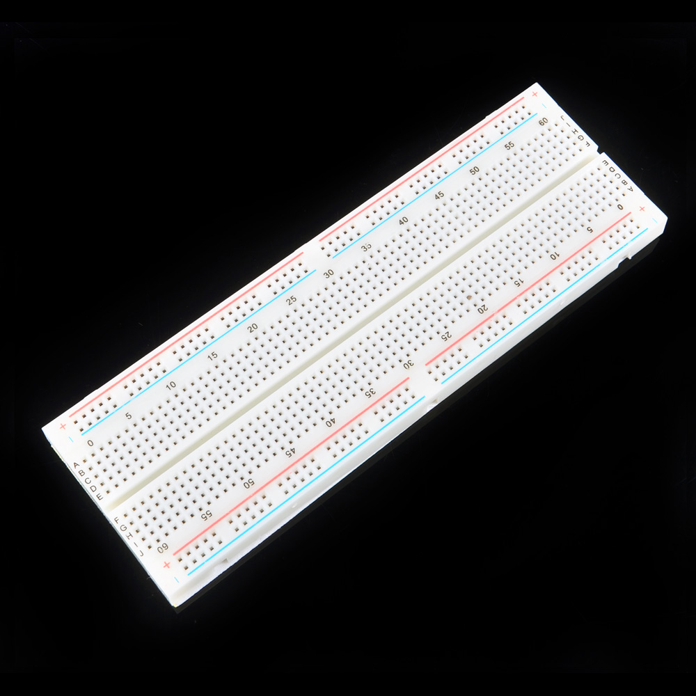
A breadboard
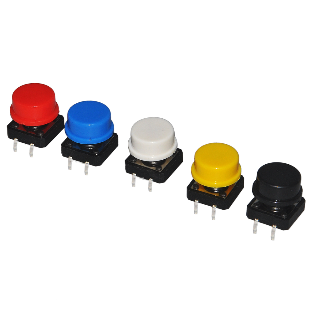
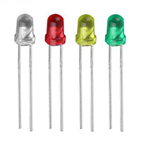
LED x 1 pc
220 Ω resistor x 1 pc
10 kΩ resistor x 1 pc
photoresistor x 1 pc
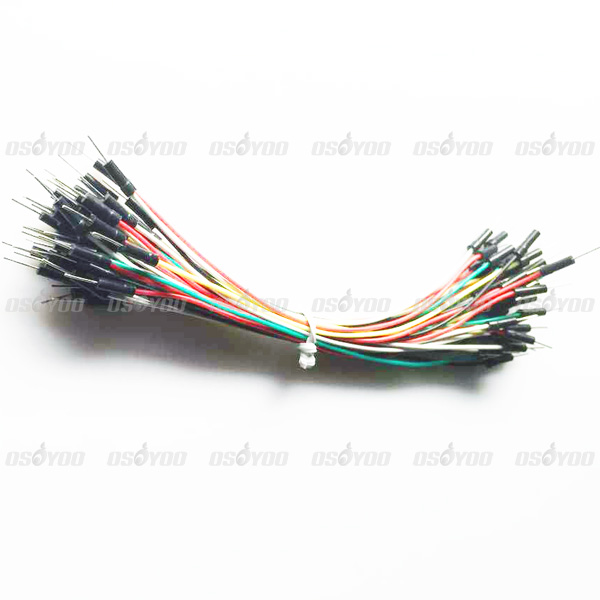
Some jumper wires
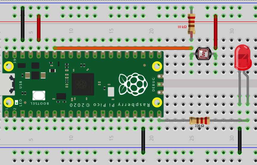
In above circuit graph, you can see that:
LED negative pin connected to GND
LED Positive pin connected to GP15 through 220 Ω resistor
photoresistance pin 1 connected to 3.3V through 10 kΩ resistor
photoresistance pin 2 connected to GP28
Making Blocks
Step 1: Create a New Project and Connect the Pico to Serial Port
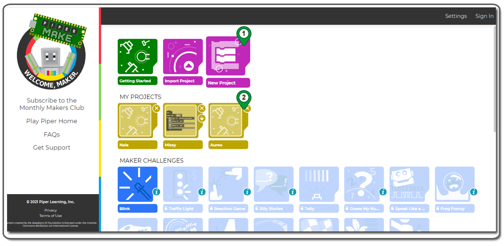
1)Click on the New Project icon. A My Project icon with a fancy name will pop up, as shown in the following picture.
2)Click the new icon in My Projects
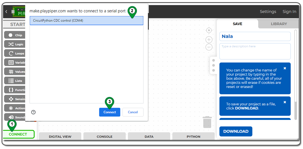
You will then enter a new graphic programming page. Please click the CONNECT button at the bottom of the page and connect your Pico board to your project. Your browser will then pop up a Serial Port option menu. Please select Pico from the menu and click the Connect button.
If you cannot see Pico in the Serial Port menu, it means your Pico is not set up properly. You need to go back to Lesson 1 Step 1 and set up the Pico again.
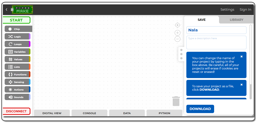
After you connect the Pico to the Serial Port, your GUI Connect button will switch to the Disconnect button, as shown in the following picture.
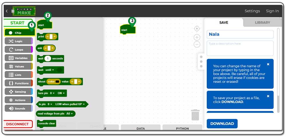
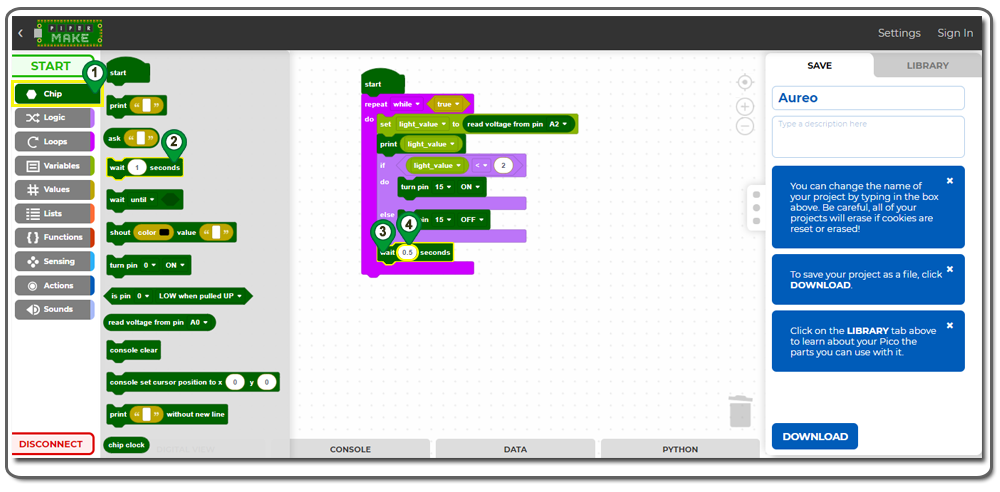
Step 2: Building Graphic Coding Chips
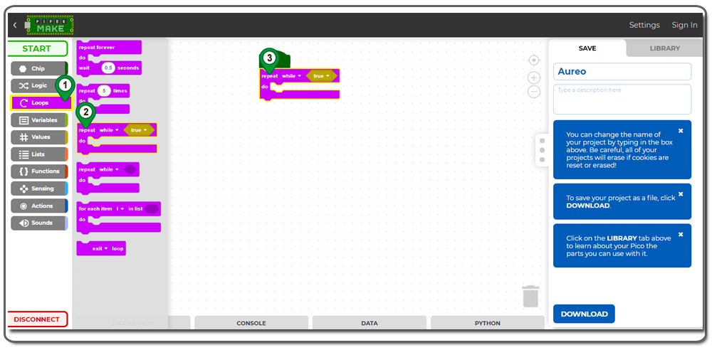
1)Click on the “Chip” option and select “Start”. Move the “Start” chip to the coding area as shown in the following picture.
2)Click on “Loops” and select “repeat while true”. Move this block just below the “Start” block.
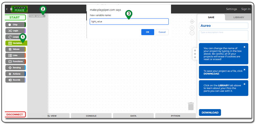
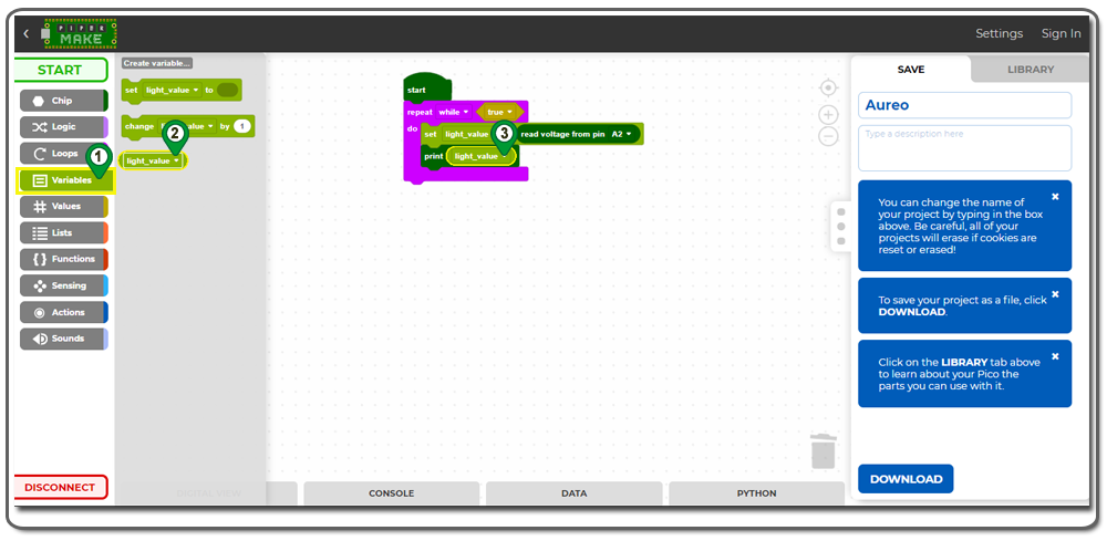
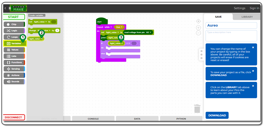
3)Now create a variable by clicking on “Variables” and selecting “Create Variable”. Name the variable “light_value” as shown in the following picture.
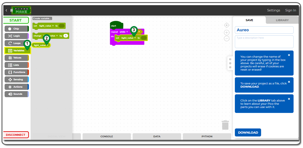
4)You will see some new variable blocks. Move the “set light_value to” block inside the “repeat while true” block as shown in the following picture
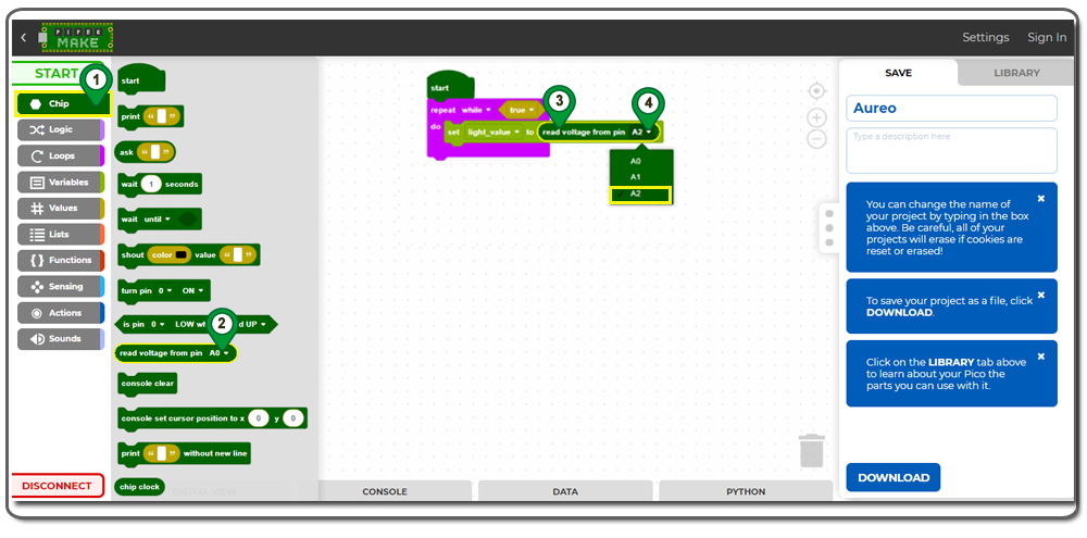
5)From the “Chip” category, add a “Read Voltage” block to the “set light_value to” block. Change the port from A0 to A2 as shown in the following picture.
Explanation: This block will read the voltage value from ADC 2 pin (GP28) and give the value to the “light_value” variable.
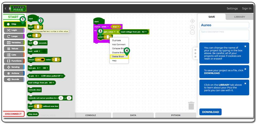
6)From the “Chip” category, add a “print” block below the “set value to” block. Right-click and delete the ” ” block inside the print block
7)From the “Variable” category, add a “light_value” block to the print block as shown in the following picture
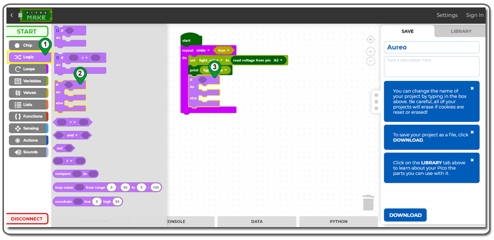
8) From the “Logic” category, add an “if_do_else” block under the print block as shown in the following picture;
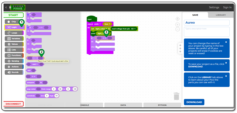
9)From the “Logic” category, add a “0=0” block under the print block as shown in the following picture.
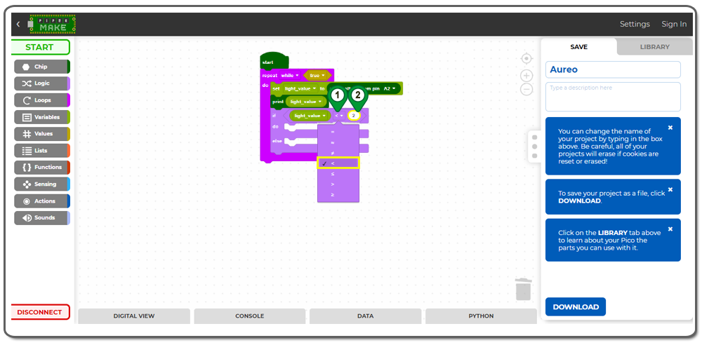
10)Click on the “Variables” category and add a “light_value” block to the “if” block as shown in the following picture;
11) Change the “=” sign to “<“, add a “0” block to the “if” block, and then change the block value from 0 to 2 as shown in the following picture;
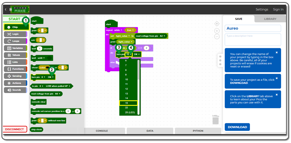
12)From the “Chip” category, add a “turn pin 0 ON” block to the “do” area. Change the pin number from 0 to 15 as shown in the following picture;
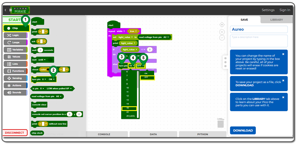
13)Add another “turn pin 0 ON” block to the “else” area. Change the pin number from 0 to 15 and change the “ON” status in the “else” area to “OFF” status as shown in the following picture.
14)From the “Chip” category, add a “Wait 1 seconds” block below the “if do else” block. Change the wait time from 1 to 0.5 as shown in the following picture;
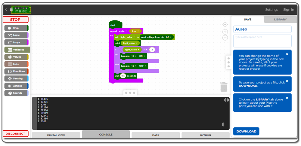
Now that we have finished building the program, we can click on the "START" button to run the program.
Step 3: Testing the Program
When the photoresistor is under bright light, the LED will turn off. When you use your hand to shield light from the sensor, the LED will turn on. This is similar to the automatic street light in your city.
You can click on the “Console” tag at the bottom to see the “light_value” printed in the console. When the light is blocked by your hand, the value is very small as shown in the following picture.


 Making Blocks