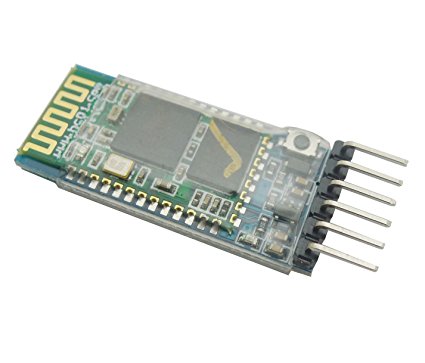
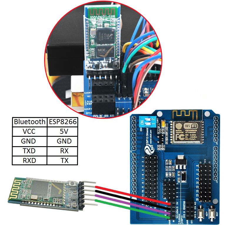
Note: Bluetooth module and Arduino board communicate with each other through UART serial port. Please remove bluetooth module before uploading sketch in Arduino board, otherwise the sketch will be uploaded unsuccessfully.
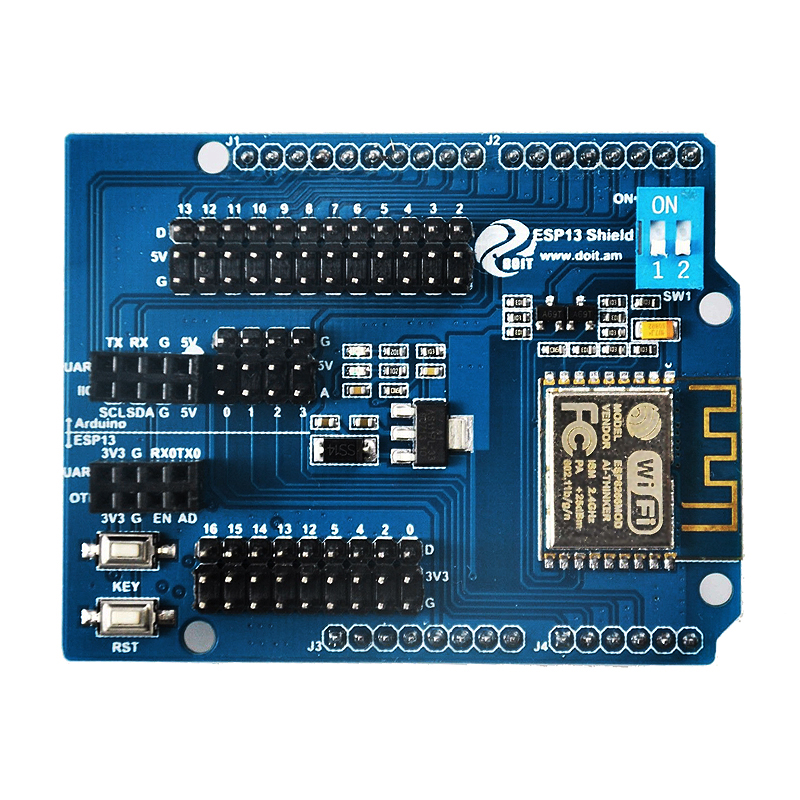
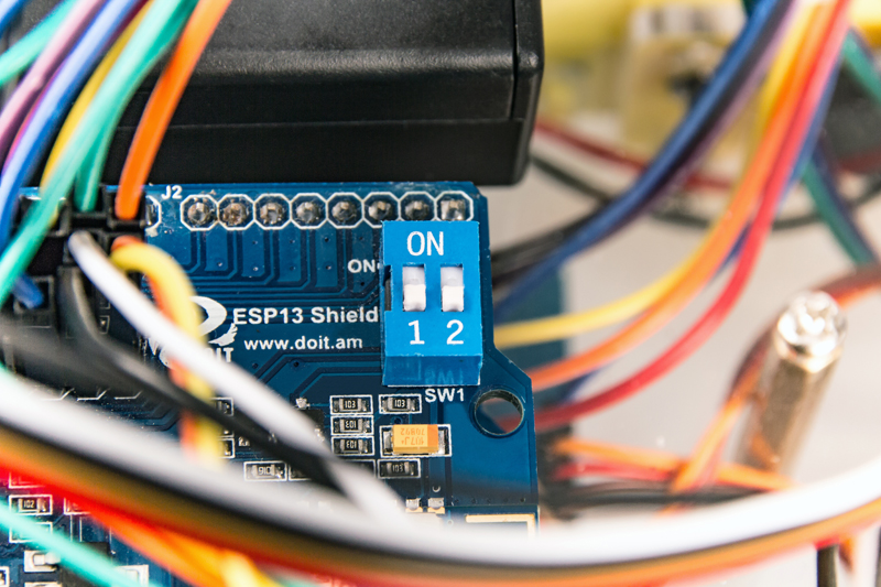
Step 5) If you want use wifi to control the car, turn the switch of esp8266 to “on” position(as the following picture). If you want use Bluetooth control car, put switch in “1,2” position.
Step 6) Turn on switch in the battery box. If there car can make movement as described in Lesson 1 (go forward 5 seconds, then go backward 5 seconds, then left turn for 5 seconds, then right turn for 5 seconds, then stop), it means wire connection with ESP8266 Expansion Board and R3 UNO board are all correct. Otherwise please check the each Digital Pin connection in ESP8266 Expansion Board and UNO R3.
Software Installation:
Step 1: Before upload code in esp8266, please turn the switch of esp8266 to “1.2” position, as following photo shows:
Step 2: Download Lesson 5 sample code from https://osoyoo.com/driver/smartcar-lesson5.zip , unzip the download zip file smartcar-lesson5.zip, you will see a folder called smartcar-lesson5.
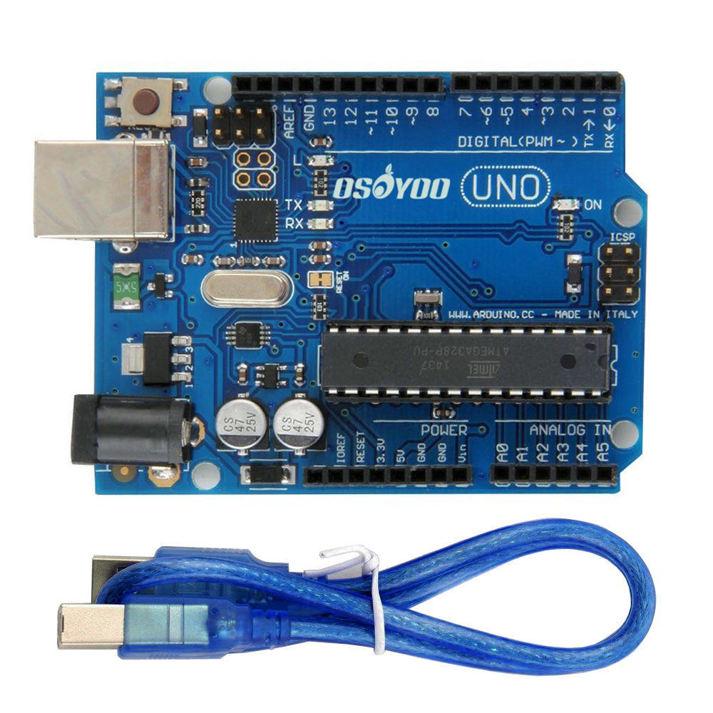
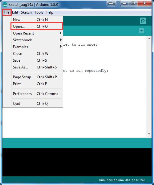
Step 3: Connect Arduino UNO to PC with USB cable, Open Arduino IDE -> click file -> click Open -> choose code “smartcar-lesson5.ino” in smartcar-lesson5 folder,, load the code into arduino.
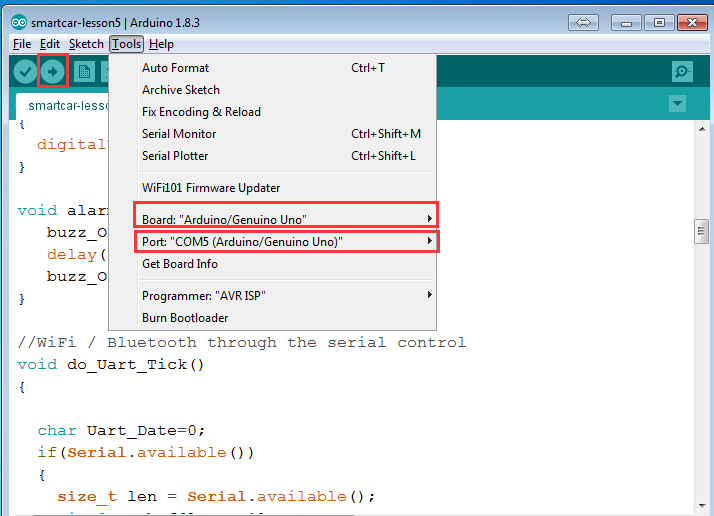
Step 4: Choose corresponding board/port for your project,upload the sketch to the board.
Note: Bluetooth module and Arduino board communicate with each other through UART serial port. Please remove bluetooth module before uploading sketch in Arduino board, or the sketch will be uploaded unsuccessfully.
Step 5: If you want use wifi to control the car, turn the switch of esp8266 to “on” position(as the following picture) and make sure Bluetooth module is NOT insert into wifi shield.
If you want use Bluetooth control car, put switch in “1,2” position.
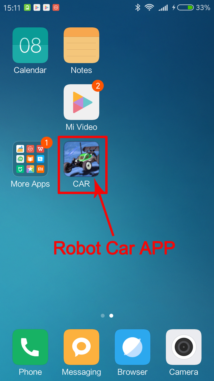
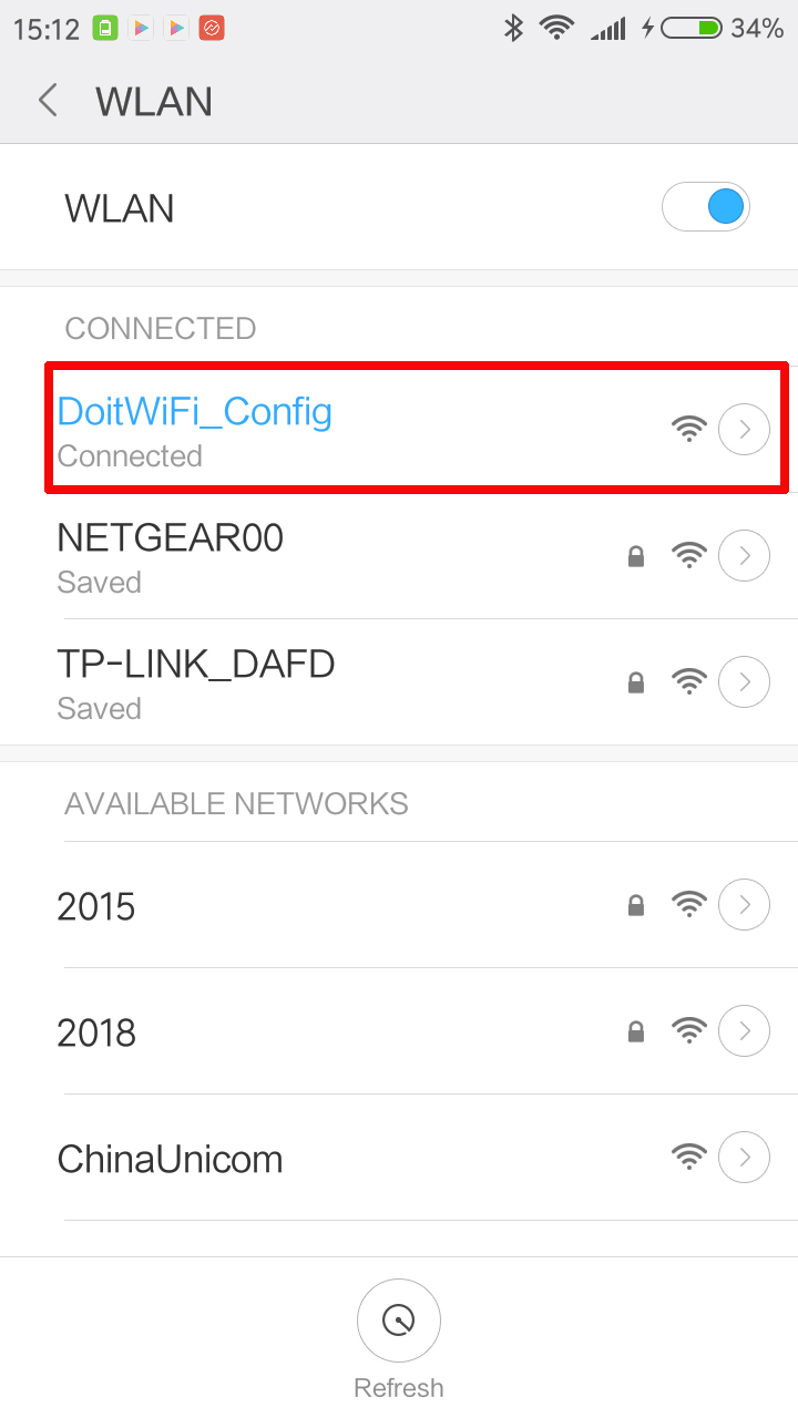
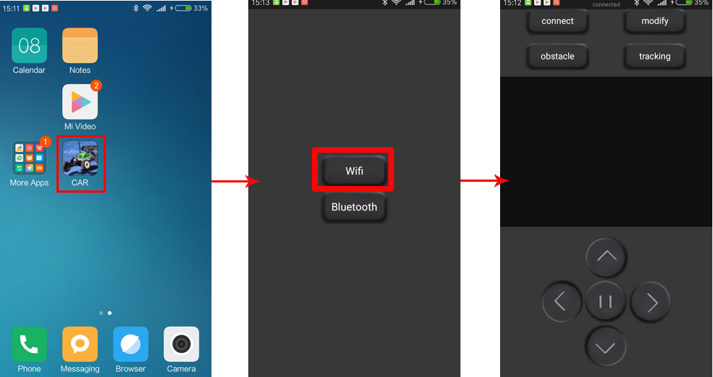
Step 2:If you want to control the robot car through WIFI, please scan WiFi hotspot with your Android phone which you have installed APP and search for wifi named” DoitWIFI_Config”, Click connect(no password needed).
Step 3: Open app>> select WiFi mode>> then you can controller the robot car through wifi
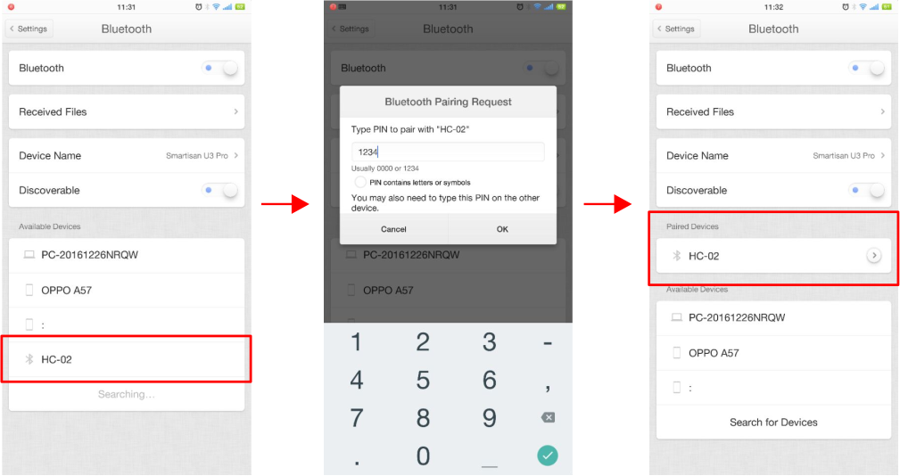
Step 4: If you want to control the robot car through Bluetooth, please put switch on esp8266 module in “1,2” position and turn on bluetooth of your Android phone which you have installed APP and scan bluetooth(different bluetooth module will scan different bluetooth name), Click connect and enter password “1234” or “0000” if no change (You can change wifi or bluetooth settings in Android phone to switch to control car through wifi or bluetooth):
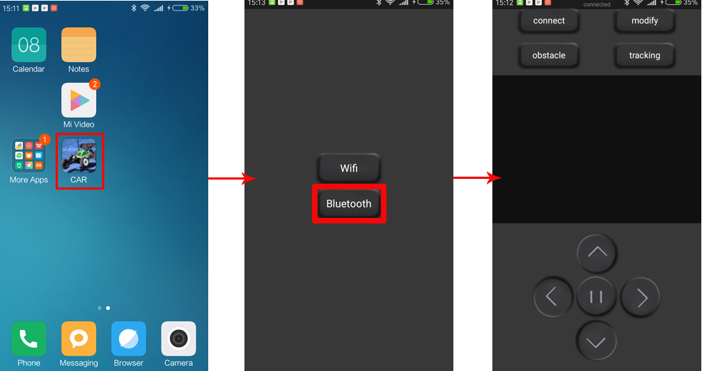
Step 5) Open app>> select bluetooth mode>> then you can controller the robot car through bluetooth:
There are three working mode: manual control, obstacle avoidance and tracking. Users can switch freely among three working mode.
1) In manual control mode, you can click buttons (^) (V) (<) (>) to control the Robot car to move forward and backward, turn right and left. Meanwhile, the APP can observe the car real time movement.
2) Click “tracking” button of App to switch the current mode to tracking mode. The Robot car will move forward along the black line in white background. Meanwhile, the APP can observe the car real time movement. Press “||” button to stop moving and click other button to change Robot car working mode. To learn more about this mode, please review our lesson 4:
3) Click “Obstacle” button to switch the current mode to obstacle avoidance mode. The Robot car can be driven forward continuously and stopped and steered away once any obstacle in its way. Press “||” button to stop moving and then click other button to change Robot car working mode. To learn more about this mode, please review our lesson 3:
I have completed all 5 lessons. I am able to use bluetooth communication with the DIP switches set to off (1.2). However, when I turn off the power, remove the bluetooth module, move the DIP switches to ON, turn power back on, restart the CAR application, select “WiFi”, connect phone to the shield’s SSID via WiFi, I am unable to get the application to connect to the car. The application only indicates that it is “disconnected”. What could I be doing wrong?
Yes. I have done that:
1. turn car power off
2. remove bluetooth card
3. flip DIP switches to “ON”
4. Turn car power on
5. Disable WiFi on phone
6. Force close CAR app
7. Enable WiFi on phone
8. Connect to “DoitWiFi_Config”
9. Launch CAR app
10. Select “WiFi” mode
Then, the app says it’s “connected” already (indicated at the top) I try a command: step forward. It works. The app immediately displays “Connection disconnect” near the bottom and the status at the top says “disconnect”. After that, the CAR app is not able to connect until I close and reopen the CAR app. Then I get to run one more command.
Also, if I disconnect and reconnect from “DoitWiFi_Config” I am able to run another *single* command without restarting the CAR app. Same result of disconnect immediately following the command.
Hi, I completed all the 5 lessons. The car worked well in the previous lessons, but now I installed wifi module and bluetooth, I connect with the phone app, and car doesn’t do anything. What can I do?
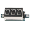
I noticed that the voltage display shows 6.8. Can be the voltage too low?
Hi, I tried all 5 lessons for the smart car kit I ordered and received about a month ago. Unfortunately, I experienced failures in two lessons. They are as follows.
(1) Lession 2 – Car does not move at all with the IR remote control although I can see LED lights brinking on IR receiver board.
(2) Lesson 5 – Wifi control does not work properly. Pushing any button (forward, back, left, or right turn) and releasing changes connected to disconnected status immediately and this forces start over with new wifi connection. This means sequential control is not possible without reconnecting wifi. Bluetooth does not work properly either. Car motion is not continuous even when you keep pushing any control buttons. Car makes short move and stop.
My phone is with android version# 8.0.0 and battery meter showed initially 8.4 and lately 7.8 volts after some trials. The product order number I got from Amazon is 112-3383311-2641052. Please let me know what needs to be done.
please to check the wire connections, modules’ installations and software installations carefully firstly,and make sure they are all right.Could you please try it? any update?
I am confident that hardware and software installation and wiring were all done correctly. I tested several times on different days after verifing correct installation and wiring and the same problems were observed.
I think the user report by Derrickoson on April 3, 2018 mentioned a problem similar to my problem in lession 5: Wifi is disconnected immediately following a *single* command.
I discarded all my old phones and cannot test android version below 4.4 as you suggested. How can I switch back to old android version with my current phone? My Samsung phone shows installed version number 8.0.0 and does not say how you can go back to old version. I am also concerned that switching back to old version might cause other functionality issues. Was the Osoyoo Smart Car designed to work only with old android version?
our engineers are updating the software of the phone app which can support android version above 4.4 these days , but it need a few days, could you please wait for some days?
Ok, fine. I can wait for the lession 5 problem. How about my lession 2 problem of no operation with remote IR control although LED lights on IR receiver board blink. Any idea what could be wrong?
Hi Elaine, thank you for the updated wifi remote control App. It works great with my latest android version. However, I still see two different problems. Bluetooth control fails to perform continuous car motion when I keep pushing control buttons: car repeats short motion. I am wondering whether Bluetooth mode in the App needs to be updated as wifi mode for new android versions. Per IR control problem for lesion 2, I checked the IR receiver board by connecting to Arduino hardware as you suggested. Demodulated hex code observed through serial monitor for control buttons such as left, up, etc. do not match with those in test program. The code is also not consistent. Doesn’t this indicate my IR receiver board is bad?
Hi, we have updated the phone app again, please uninstall the previous APP, then download the newest app. then to try Bluetooth fuction again, any update?
As for Per IR control problem, please offer the hex code of top, down, right, left.
Kwangcho, to help you solve the problem sooner, could you reply us by email to [email protected] . If this is our hardware problem, we will send you replacement to you, and if this is software set up problem, we will give you guide to reinstall the program.
hi , again , tracking mode dont work good it always go out line , and i havent 90 degree lines . i tryed to lower the spedd of the car but dont work too
how can i do ??
I have a problem in Bluetooth mode. When I start the app and connect to bluetooth it says ” connected you have modified the parameters.I have no idea what happen or how to clear it, what it does it will not let the car continually go forward, you have to hit the button each time to move it forward.Any help would be appreciated.
yes. the car is designed to move a short distance after each hit. We do this because we do not want the car moving too fast otherwise it might hit obstacle and damage. If you want to longer movement after one hit, you might need customize the code in void do_Drive_Tick() function. Try different value for JogTimeCnt and see the result.
In wifi if I hold the forward button it will continue moving until I let it go. I did notice on the screen in Bluetooth it will display forward on the phone screen, but in Wifi it shows a . I don’t know what that means. If I haven’t hooked up to the computer why is it saying”connected you have modified the parameters” What parameters is it talking about?


I have completed all 5 lessons. I am able to use bluetooth communication with the DIP switches set to off (1.2). However, when I turn off the power, remove the bluetooth module, move the DIP switches to ON, turn power back on, restart the CAR application, select “WiFi”, connect phone to the shield’s SSID via WiFi, I am unable to get the application to connect to the car. The application only indicates that it is “disconnected”. What could I be doing wrong?
Do you go to phone setting to connect wifi and restart the APP?
Yes. I have done that:
1. turn car power off
2. remove bluetooth card
3. flip DIP switches to “ON”
4. Turn car power on
5. Disable WiFi on phone
6. Force close CAR app
7. Enable WiFi on phone
8. Connect to “DoitWiFi_Config”
9. Launch CAR app
10. Select “WiFi” mode
Then, the app says it’s “connected” already (indicated at the top) I try a command: step forward. It works. The app immediately displays “Connection disconnect” near the bottom and the status at the top says “disconnect”. After that, the CAR app is not able to connect until I close and reopen the CAR app. Then I get to run one more command.
Also, if I disconnect and reconnect from “DoitWiFi_Config” I am able to run another *single* command without restarting the CAR app. Same result of disconnect immediately following the command.
Are you willing to tell me the version of your Android?
i have the same problem, and i don’t know how to solve it
I need an answer as soon as possible
I think the wifi expansion board may be defective.
Are you willing to provide your order No. and I’ll send the board to you and please have a try.
OK?
Hi, I completed all the 5 lessons. The car worked well in the previous lessons, but now I installed wifi module and bluetooth, I connect with the phone app, and car doesn’t do anything. What can I do?
I noticed that the voltage display shows 6.8. Can be the voltage too low?
1. Do you mean the wifi and bluetooth module can’t work as the tutorial?
2. The voltage need more than 7V and then the car will work smoothly.
Yes, the car doesn’t move. I can’t control the car with the app. How can I solve?
Which version Android of your phone is?
Do you put the swtich to on when it work on wifi?
My phone has Android 4.3
Yes, I put the switch to on wifi.
Which can be the problem?
I think the wifi expansion board may be defective.
Are you willing to provide your order No. and I’ll send the board to you and please have a try.
OK?
OK, my order number is 171-5077738-6650706. From Amazon.
ok, we will reship the board to you today and give you the tracking number via amazon email massage.
Ok
Hi, I completed the car. But I think it goes too fast, and before avoid obstacles it bangs on them. How can I do?
Hi, I tried all 5 lessons for the smart car kit I ordered and received about a month ago. Unfortunately, I experienced failures in two lessons. They are as follows.
(1) Lession 2 – Car does not move at all with the IR remote control although I can see LED lights brinking on IR receiver board.
(2) Lesson 5 – Wifi control does not work properly. Pushing any button (forward, back, left, or right turn) and releasing changes connected to disconnected status immediately and this forces start over with new wifi connection. This means sequential control is not possible without reconnecting wifi. Bluetooth does not work properly either. Car motion is not continuous even when you keep pushing any control buttons. Car makes short move and stop.
My phone is with android version# 8.0.0 and battery meter showed initially 8.4 and lately 7.8 volts after some trials. The product order number I got from Amazon is 112-3383311-2641052. Please let me know what needs to be done.
Sincerely
Kwang Cho
please to check the wire connections, modules’ installations and software installations carefully firstly,and make sure they are all right.Could you please try it? any update?
I am confident that hardware and software installation and wiring were all done correctly. I tested several times on different days after verifing correct installation and wiring and the same problems were observed.
Could you please change a phone which android version below 4.4 to try it, any update?
I think the user report by Derrickoson on April 3, 2018 mentioned a problem similar to my problem in lession 5: Wifi is disconnected immediately following a *single* command.
Could you please change a phone which android version below 4.4 to try it, any update?
I discarded all my old phones and cannot test android version below 4.4 as you suggested. How can I switch back to old android version with my current phone? My Samsung phone shows installed version number 8.0.0 and does not say how you can go back to old version. I am also concerned that switching back to old version might cause other functionality issues. Was the Osoyoo Smart Car designed to work only with old android version?
our engineers are updating the software of the phone app which can support android version above 4.4 these days , but it need a few days, could you please wait for some days?
Ok, fine. I can wait for the lession 5 problem. How about my lession 2 problem of no operation with remote IR control although LED lights on IR receiver board blink. Any idea what could be wrong?
please visit: https://osoyoo.com/2017/07/20/arduino-lesson-ir-remotecontrol/?preview_id=9211&preview_nonce=aeac5d434c&_thumbnail_id=14649&preview=true
and check whether the infrared receiver and infrared remote control are in good condition or not?
we have updated the phone app which can support android version above 4.4, please uninstall the previous APP, then download the new app. in Android phone from the link: https://raw.githubusercontent.com/osoyoo/driver/master/BTcar.apk.
Hi Elaine, thank you for the updated wifi remote control App. It works great with my latest android version. However, I still see two different problems. Bluetooth control fails to perform continuous car motion when I keep pushing control buttons: car repeats short motion. I am wondering whether Bluetooth mode in the App needs to be updated as wifi mode for new android versions. Per IR control problem for lesion 2, I checked the IR receiver board by connecting to Arduino hardware as you suggested. Demodulated hex code observed through serial monitor for control buttons such as left, up, etc. do not match with those in test program. The code is also not consistent. Doesn’t this indicate my IR receiver board is bad?
Hi, we have updated the phone app again, please uninstall the previous APP, then download the newest app. then to try Bluetooth fuction again, any update?
As for Per IR control problem, please offer the hex code of top, down, right, left.
Kwangcho, to help you solve the problem sooner, could you reply us by email to [email protected] . If this is our hardware problem, we will send you replacement to you, and if this is software set up problem, we will give you guide to reinstall the program.
please visit: https://osoyoo.com/2017/07/20/arduino-lesson-ir-remotecontrol/?preview_id=9211&preview_nonce=aeac5d434c&_thumbnail_id=14649&preview=true
and check whether the infrared receiver and infrared remote control are in good condition or not?
Hi, I completed the car. But I think it goes too fast, and before avoid obstacles it bangs on them. How can I do?
hi , again , tracking mode dont work good it always go out line , and i havent 90 degree lines . i tryed to lower the spedd of the car but dont work too
how can i do ??
I have a problem in Bluetooth mode. When I start the app and connect to bluetooth it says ” connected you have modified the parameters.I have no idea what happen or how to clear it, what it does it will not let the car continually go forward, you have to hit the button each time to move it forward.Any help would be appreciated.
yes. the car is designed to move a short distance after each hit. We do this because we do not want the car moving too fast otherwise it might hit obstacle and damage. If you want to longer movement after one hit, you might need customize the code in void do_Drive_Tick() function. Try different value for JogTimeCnt and see the result.
In wifi if I hold the forward button it will continue moving until I let it go. I did notice on the screen in Bluetooth it will display forward on the phone screen, but in Wifi it shows a . I don’t know what that means. If I haven’t hooked up to the computer why is it saying”connected you have modified the parameters” What parameters is it talking about?