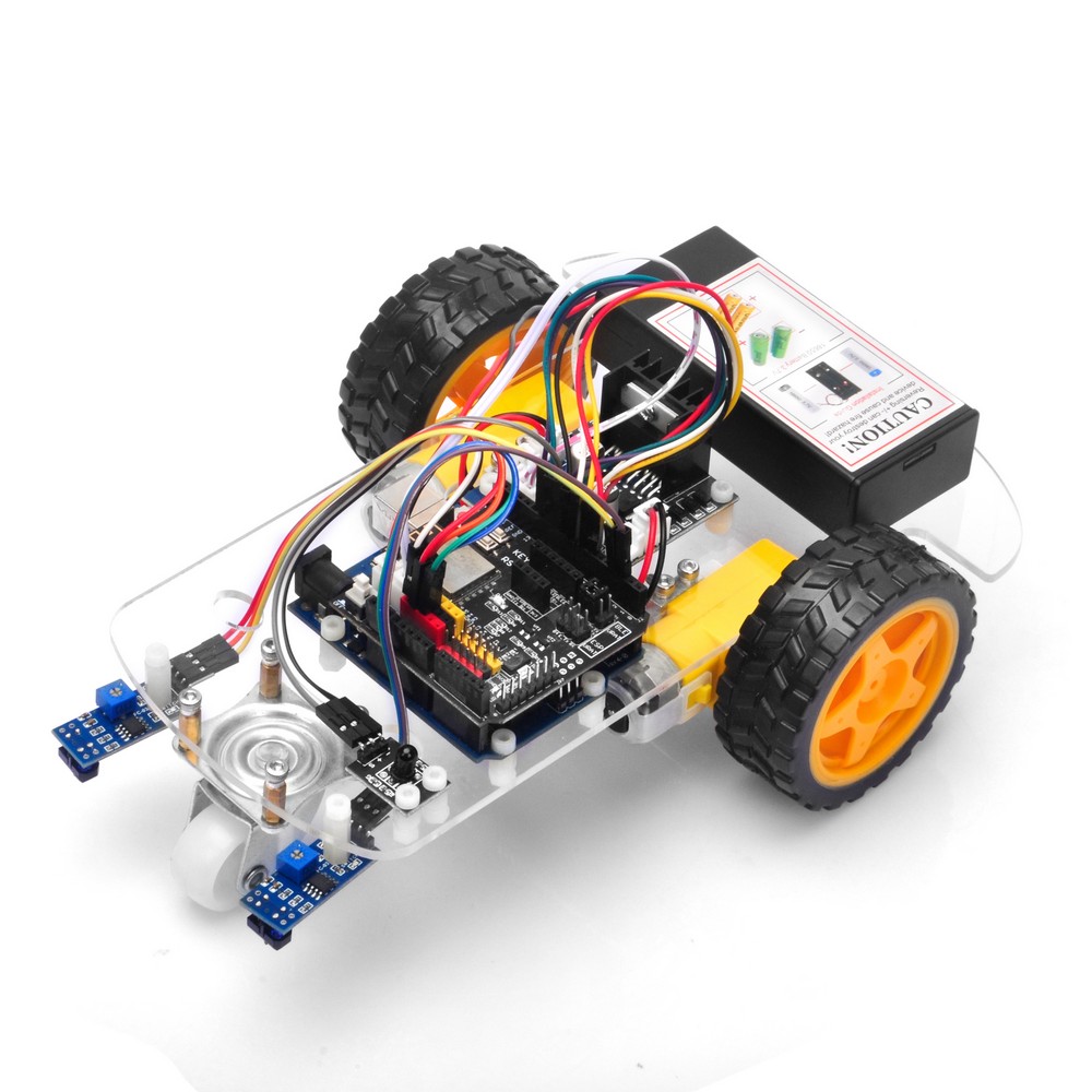
Welcome to the third lesson of OSOYOO 2WD Robot Car Starter Kit!
Install the robot car basic framework as per Lesson 1. If you have already completed the installation in Lesson 1, just keep it, no need to remove any module installed.
The software in this lesson will read data from these 2 black/white tracking sensors and automatically guide the 2WD Robot Car to move along the black track line in the white ground.
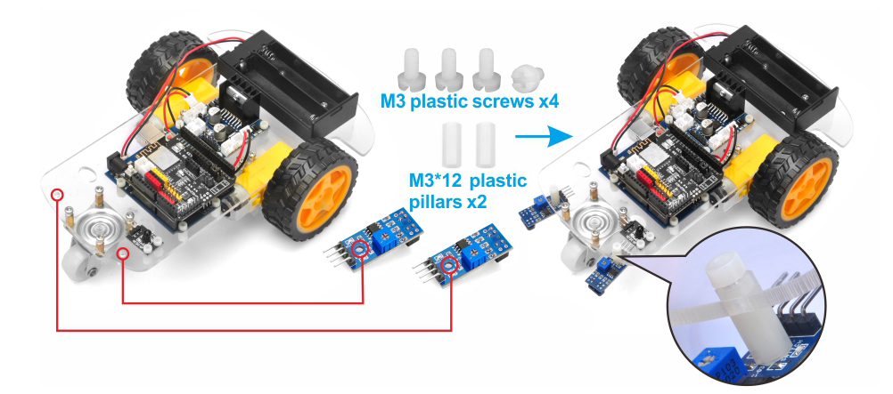
Hardware Installation
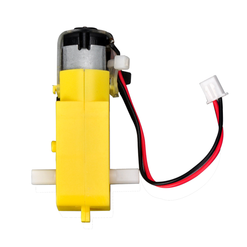
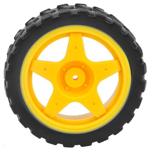
1) Install the 2WD Robot Car Chassis
Install the smart car basic framework as per 2WD Robot Car Starter KitLesson 1. If you have already completed installation in Lesson 1, just keep it, no need to remove any module installed.
More information about this module please refer to:
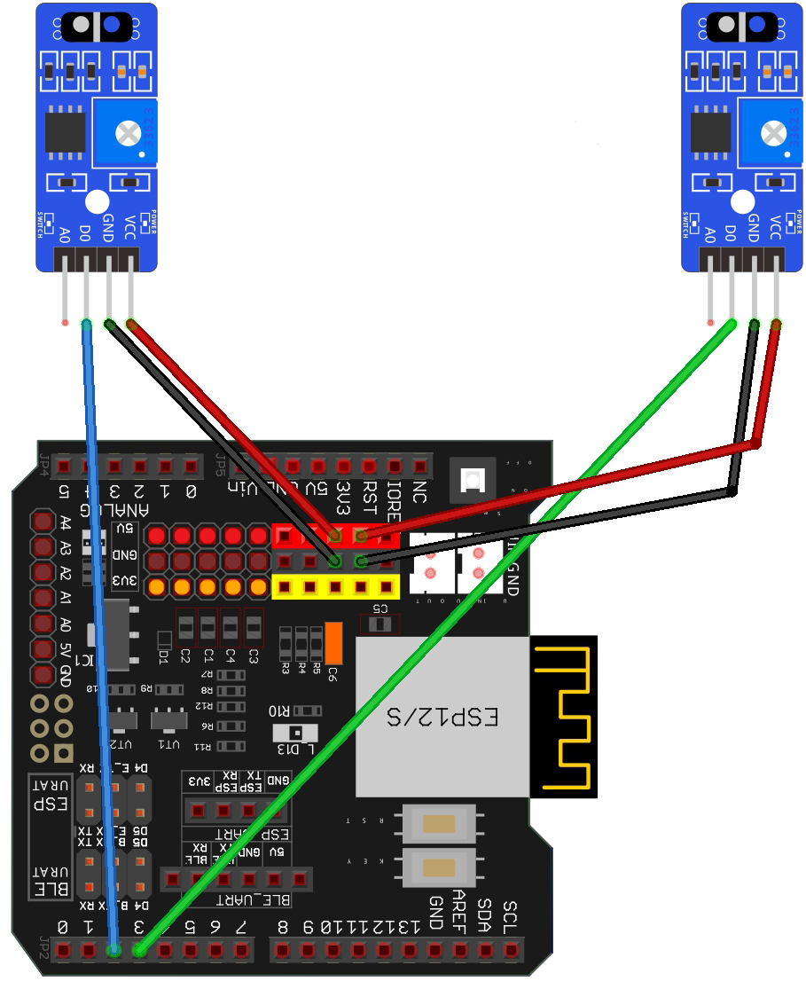
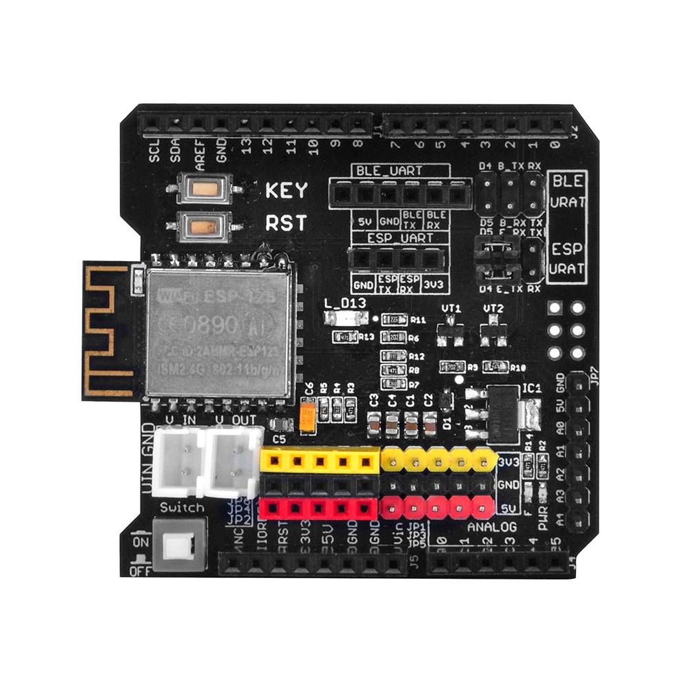
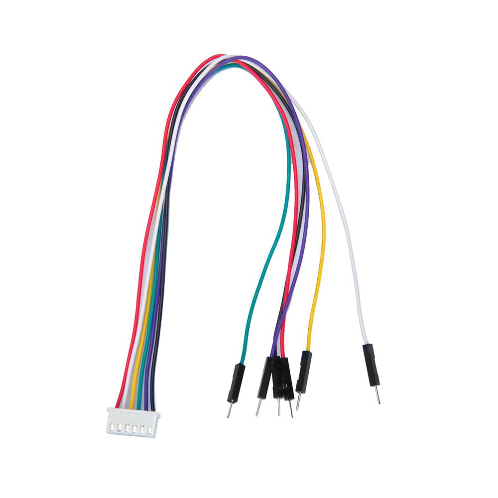
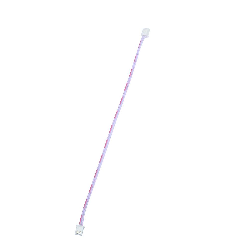
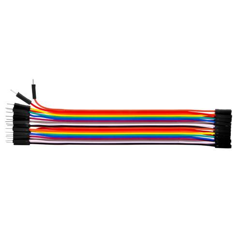
Connect OSOYOO UART Wi-Fi Shield with the tracking sensor:
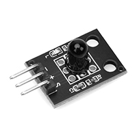
The Lest Tracking Sensor
Tracking Sensor
Sensor Shield V5.0 for Arduino UNO
VCC
5V
GND
GND
DO
S2
AO
Not Connected
The Right Tracking Sensor
Tracking Sensor
Sensor Shield V5.0 for Arduino UNO
VCC
5V
GND
GND
DO
S3
AO
Not Connected
Software Installation
Notice: Shut off your battery or unplug your power adapter when upload sketch code to Arduino.
Step 1: Install latest Arduino IDE (If you have Arduino IDE version after 1.1.16, please skip this step). Download Arduino IDE from https://www.arduino.cc/en/Main/Software?setlang=en, then install the software.
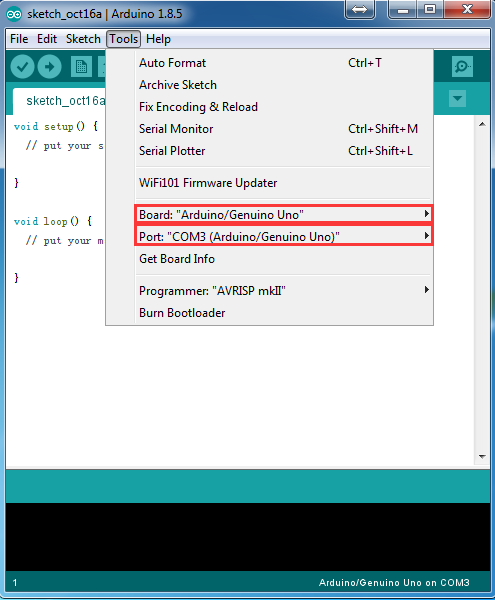
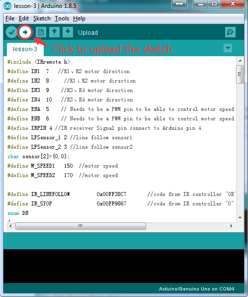
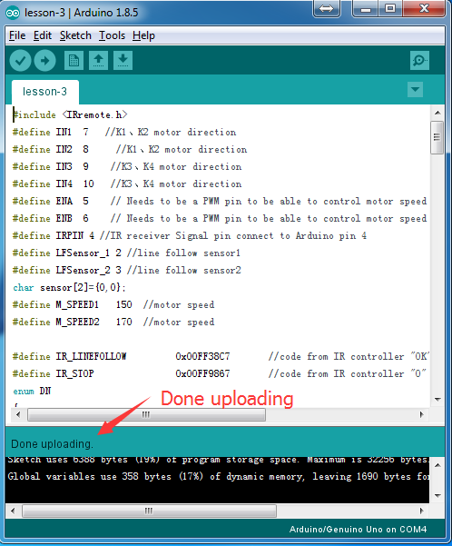
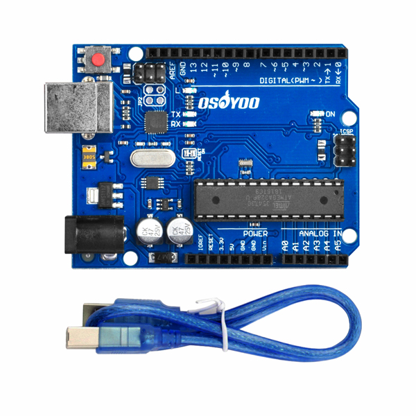
Step 3: Connect UNO R3 board to PC with USB cable, open Arduino IDE, choose corresponding board/port for your project, upload the sketch to the board.
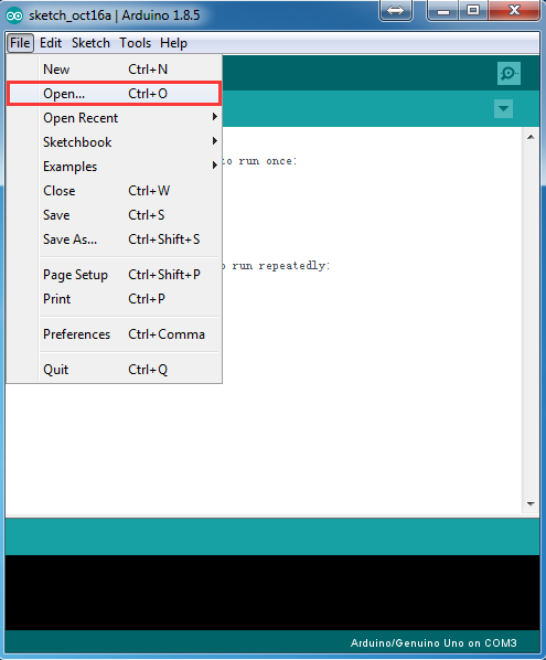
Step 4: Arduino IDE: Click file → click Open → select code “lesson-3.ino” in lesson-3 folder, load the code into Arduino.
Code Explanation
Line 19/20 Definitions between tracking sensor, D3 connect to Right Sensor, D2 to Left Sensor:
#define RightSensor 3
#define LeftSensor 2
The following two variables represent the lasting time(mini-seconds) of the car left/right turning, if the time is longer, the turning angle is sharper:
#define RIGHT_TIME 15
#define LEFT_TIME 15
The read_sensor() function will detect the left /right sensors are in black or white area. Tracking sensor will return 1 when it is over black area(track line) or return 0 when it is in white ground. So, read_sensor() function will set the 0/1 value to two variables : left_status and right_status. For example, if left_status value is zero and left_status value is 1, it means the car right side has touched the black line. In this case, we will force the car to make a right turn.
The core function of this project is auto_tracking() function. The principle of this function is as follows:
1)When left sensor detected black and right sensor detected white, it means car left side touched black line, make left turn.
2)When right sensor detected black and left sensor detected white, it means car right side touched black line, make right turn.
3)if both sensors are in white area, it means the black line is in the middle of two sensors, move forward.
4)If both sensors are in black area, it means the car touch Black Stop Line, car stop.
Testing
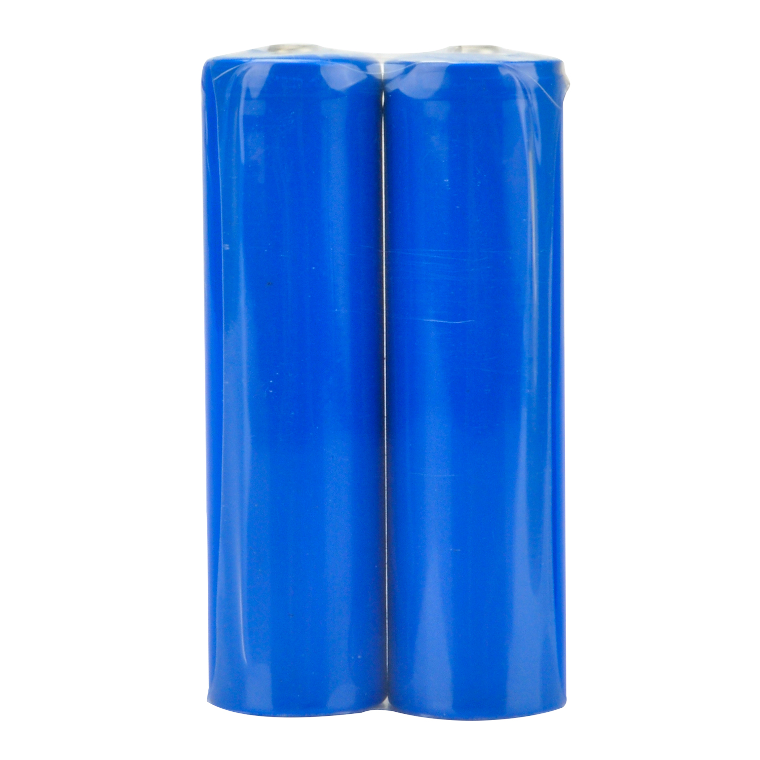
Disconnect OSOYOO UNO R3 board from PC, put 2 fully-charged 18650 battery into battery box (check the box instruction and make sure polar direction is correct). Open the power switch in the battery box.
Step 1: Prepare a black track on white ground. (the width of the black track is more than 20 mm and less than 30 mm)
Please note, the bend angle of the track can’t be larger than 90 degree. If the angle is too large, the car will move out of the track.
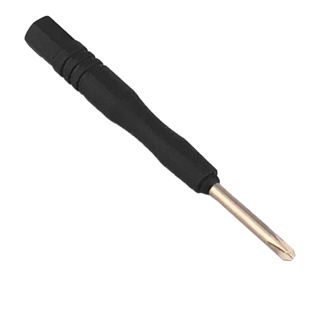
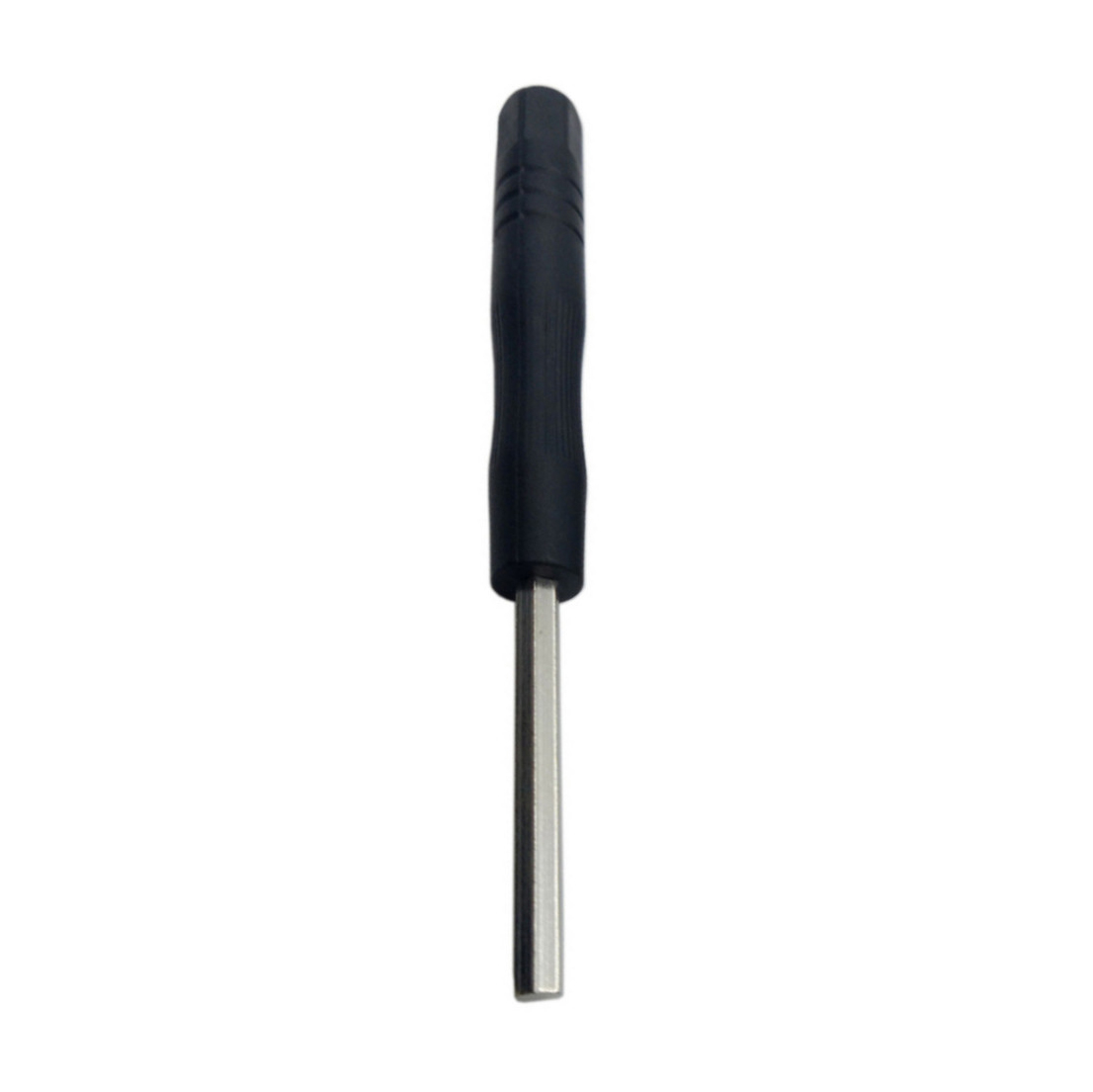
Step 2: Adjust the sensitivity of tracking sensor modules.
Turn on and hold the car to adjust the potentiometer on the tracking sensor with Phillips screwdriver until you get the best sensitivity status: the signal indicates LED light will turn on when the sensor is above white ground, and the signal LED
will turn off when the sensor is above black track.
Signal Indicate LED ON: White Ground
Signal Indicate LED OFF: Black Track
Step 3: Turn on the car and put the car over the black track, then the car will move along the black track.
If the car can’t move, please check the following:
If the battery can work;
If the connection is right;
If adjusted well the sensibility of the tracking sensor


adf