Note: ALL OSOYOO Products for Arduino are Third Party Board which is fully compatitable with Arduino
Authorized Online Retailers:
Content
-
- What is Arduino?
- Why choose Arduino?
- Types of Arduino
- What Is Inside an Arduino / What’s on the board?
- What is the Arduino IDE?
What is Arduino?
Arduino is basically an open source electronics archetype platform for electronics engineers, hobbyist, designers or anyone interested in creating interactive electronics projects. It is a flexible platform and based on an easy to use software and hardware systems. Arduino comprises of a microcontroller and a software or Integrated Development Environment (IDE) that runs on laptops or computers, used for writing and uploading computer codes or programs to the physical board.
The Arduino boards are able to read inputs – light, proximity or air quality on a sensor, or an SMS or Twitter message – and turn it into an output – activating a motor, turning on a light, publishing content online or trigger external events. You can tell your board what to do by writing code and uploading it to the microcontroller on it using the Arduino programming language (based on Wiring), and the Arduino Software (IDE), based on Processing.
Over the years Arduino has powered thousands of projects. Arduino has gathered around a community where beginners and experts from around the world share ideas, knowledge and their collective experience. There are thousands of makers, students, artists, designers, programmers, researchers, professionals and hobbyists worldwide who use Arduino for learning, prototyping, and finished professional work production.
Arduino was born at the Interaction Design Institute Ivrea IDII from the Wiring project as an easy tool for fast prototyping, aimed at students without a background in electronics and programming. The main objective of both projects is to make the process of working with technology and electronics easier. The Arduino board has evolved to adapt to new needs ranging from simple 8-bit boards to products ready for IoT applications. All Arduino boards are completely open-source, empowering users to build them independently and eventually adapt them to their particular needs. The software is open-source, and it is growing through the contributions of developers and the Arduino community worldwide.
There have been many similar projects, but none of them succeeded as well as Arduino has, due to how easy it is to use the software, and the affordability of the hardware. The Arduino software is easy-to-use for beginners, yet flexible enough for advanced users needs. It runs on Mac, Windows, and Linux.
Why choose Arduino?
Today there are many different types of microcontrollers are available in the market. So why choose Arduino? It’s an important question… Some points for Why choose Arduino are given below.
- Unlike other programmable circuit boards or microcontroller board, Arduino doesn’t require a separate hardware or programmer parts to load a code on to the board, instead of these you just need a USB cable.
- Furthermore, the Arduino IDE utilizes a simplified sort of C++, so you can easily learn the programming sections.
- Arduino supports a standard form factor.
- Working with Arduino does not require any previous experience.
- For amateurs, Arduino offers a wonderful platform for their projects ideas.
- Inexpensive compared to similar boards.
- Simplicity of ardunio compared to others.
- It is an open source platform. So any one can modify and build your own Arduino board.
- Arduino is based on Atmel’s ATMEGA168 and ATMEGA8 microcontrollers.
- Experts can easily make improvements and extensions on to the Arduino board.
Types of Arduino
Arduino has many boards it starts from basic Arduino UNO and goes to Arduino mega, ArduinoFio, lily pad so on and so forth.
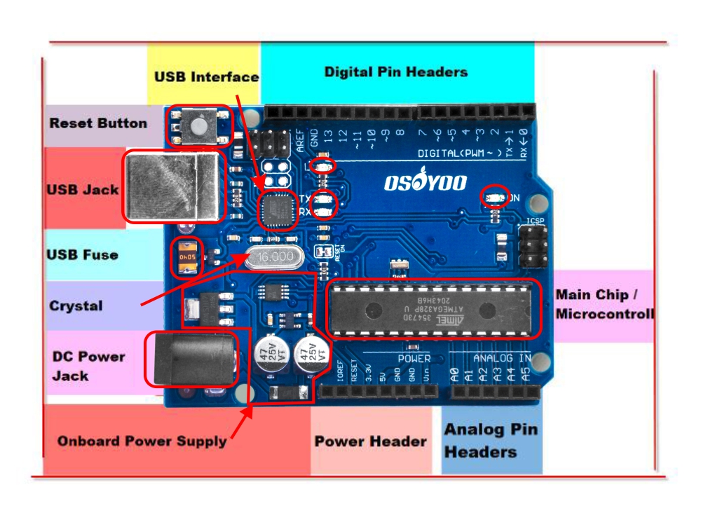
What Is Inside an Arduino / What’s on the board?
Don't feel like you have to understand this part fully! Skim it for now,
and consider it a resource for you when you want to take a deeper dive
into understanding the hardware!
Main Chip / Microcontroller
The black thing with all the metal legs is an IC, or Integrated Circuit (13). Think of it as the brains of our Arduino. The main IC on the Arduino is slightly different from board type to board type, but is usually from the ATmega line of IC’s from the ATMEL company. This can be important, as you may need to know the IC type (along with your board type) before loading up a new program from the Arduino software. This information can usually be found in writing on the top side of the IC. If you want to know more about the difference between various IC’s, reading the datasheets is often a good idea.
<h3″>Power (USB / Barrel Jack)
Every Arduino board needs a way to be connected to a power source. The Arduino UNO can be powered from a USB cable coming from your computer or a wall power supply that is terminated in a barrel jack.
The USB connection is also how you will load code onto your Arduino board. More on how to program with Arduino can be found in our Installing and Programming Arduino tutorial.
NOTE: Do NOT use a power supply greater than 20 Volts as you will overpower (and thereby destroy) your Arduino. The recommended voltage for most Arduino models is between 6 and 12 Volts.
Onboard Power Supply
The Arduino is designed for beginners so it has some protection and regulation circuitry so that it can use just about any power supply you throw at it. In particular there is a polarity protection diode (to avoid destroying the board if you have a Negative Tip adapter). It also has an onboard 5V
USB Jack & Interface
USB Jack
As we talked about in the beginning, this is how you connect your Arduino to your computer. You can use any computer with a USB port. You will need a cable to connect! This cable is usually included in the Osoyoo pack.
</h3″>
USB Inteface Chip
OK so you plug your Arduino into a computer with a USB cable. But you may be surprised to learn, the main processor chip (ATmega328) cannot speak “USB”. Instead it can talk an interface language called “Serial”. Serial is a much simpler, much older interface. (It’s also a lot less expensive to build into a chip) So, how do you connect a chip that does not speak USB to a USB port? Easy! you just need a USB to Serial Interface Translator chip. Much like a human translator, it can understand and speak both languages and can seamlessly translate between the two.
There’s a lot of different translator chips, some common part numbers are FTDI FT232, FTDI FT231X, CP2102 orCP2104, PL2303, CH430 and probably a dozen others. They’re all nearly identical but some require different operating system drivers.
Arduino LEDs
Likewise, the Arduino has four LEDs: L, RX, TX, and ON
ON LED
This LED will shine green whenever the Arduino is powered. Always check this LED if your Arduino is not acting right, if its flickering or off then you should check your power supply.
RX and TX LEDs
These are like the ‘send’ and ‘receive’ LEDs on your cable modem. They blink whenever information is sent from or to the Arduino through the USB connection
The TX LED lights up yellow whenever data is sent from the Arduino to the computer USB port
The RX LED lights up yellow whenever data is sent to the Arduino from the computer USB port
L LED
This is the one LED that you can control. The ON, RX and TX LEDs all light up automatically no matter what. The L LED, however, is connected to the Arduino main chip and you can turn it on or off when you start writing code.
For future reference, L is connected to Digital Pin #13
Power Header
- Vin – This is connected to the power input from the DC Jack, so it is going to range from 7 V to 12 VDC, depending on what is plugged into the DC Jack. If the DC Jack is not powered, it will provide the 5V from the USB connection. Provides as much as the DC power supply can.
- GND – You get two of these here, they are the common ground connection for all power and data
- 5V – This is the clean regulated 5V power that the Arduino runs on, provided from the DC jack (if plugged in) or USB connection (if DC is not plugged in). Provides up to about 500mA current draw.
- 3.3V – This is a clean regulated 3.3V power, sometimes you’ll need exactly this voltage for some sensors. Provides up to about 100mA current draw.
- Reset – This is the same pin connected to the reset button
- IOref – Used by shields to know what the IO voltage is. You can ignore this pin.
- Unnamed pin – Reserved for future use, don’t connect to it!
Digital Pin Headers
The two pins labeled 0 (RX) and 1 (TX) are the two Serial pins that are used to send data to and from the Arduino to the USB-Serial translator chip.
Don’t connect anything to Digital 0 or 1 unless you are super sure because it will affect your Arduino’s ability to communicate!
- Digital 2 through Digital 12 are normal every day digital pins.
- PWM Pins: In the board, there is a ~ sign near to some of the pins – 3, 5, 6, 9, 10(digital pins) and 11 on the UNO Arduino. Actually these pins are normal digital pins but it can be used for Pulse-Width Modulation (PWM) also.
- Digital 13 is a little special because it is also connected to the L LED. You can use this pin without affecting the Arduino just be aware that the L LED will also blink at the same time.
And a few extra straggler pins:
- A spare power GND Ground pin
- AREF – Analog Reference pin. Used for advanced analog sensor reading (You’ll learn about this later)
- Two unlabeled pins (the labels are on the bottom). These are the SDA and SCL pins, which are used for connecting I2C type sensors. They are connected inside the PCB to A5 and A4 We do not recommend usin these unless you have an I2C sensor
Analog Pin Headers
Shh! It’s a secret but those 6 analog input pins? They can also be used as digital input/output pins, they really are the most versatile pins!
Each analog pin can read a voltage between 0 and 5 V (the same voltage used to power the Arduino.
Once you get advanced analog skills you can connect the ARef pin to a different voltage like 3.3V and direct the Arduino to use Aref as the max voltage, then you can get more precision. But we’ll cover that some other day.
Do not connect a voltage higher than 5V to the analog input pins or you could damage them!
USB Fuse
The little USB fuse is a part that is used to protect your Arduino and computer. You’ll be connecting all sorts of wires to your Arduino and there’s a chance you will accidentally short out the power. To keep your electronics safe this resettable fuse will open up, much like the circuit breakers in your home.
Reset Button
Just like the original Nintendo, the Arduino has a reset button (10). Pushing it will temporarily connect the reset pin to ground and restart any code that is loaded on the Arduino. This can be very useful if your code doesn’t repeat, but you want to test it multiple times. Unlike the original Nintendo however, blowing on the Arduino doesn’t usually fix any problems.
Pins (5V, 3.3V, GND, Analog, Digital, PWM, AREF)
The pins on your Arduino are the places where you connect wires to construct a circuit (probably in conjuction with a breadboard and some wire. They usually have black plastic ‘headers’ that allow you to just plug a wire right into the board. The Arduino has several different kinds of pins, each of which is labeled on the board and used for different functions.
- GND (3): Short for ‘Ground’. There are several GND pins on the Arduino, any of which can be used to ground your circuit.
- 5V (4) & 3.3V (5): As you might guess, the 5V pin supplies 5 volts of power, and the 3.3V pin supplies 3.3 volts of power. Most of the simple components used with the Arduino run happily off of 5 or 3.3 volts.
- Analog (6): The area of pins under the ‘Analog In’ label (A0 through A5 on the UNO) are Analog In pins. These pins can read the signal from an analog sensor (like a temperature sensor) and convert it into a digital value that we can read.
- Digital (7): Across from the analog pins are the digital pins (0 through 13 on the UNO). These pins can be used for both digital input (like telling if a button is pushed) and digital output (like powering an LED).
- PWM (8): You may have noticed the tilde (~) next to some of the digital pins (3, 5, 6, 9, 10, and 11 on the UNO). These pins act as normal digital pins, but can also be used for something called Pulse-Width Modulation (PWM). We have a tutorial on PWM, but for now, think of these pins as being able to simulate analog output (like fading an LED in and out).
- AREF (9): Stands for Analog Reference. Most of the time you can leave this pin alone. It is sometimes used to set an external reference voltage (between 0 and 5 Volts) as the upper limit for the analog input pins.
What is the Arduino IDE?
Arduino provides an open-source and easy-to-use programming tool for writing code and uploading it to your board. It is often referred to as the Arduino IDE (Integrated Development Environment). The Arduino Software (IDE) is easy-to-use for beginners, yet flexible enough for advanced users.


