Overview
The OSOYOO UART LoRa wireless module is a long range transceiver on a Arduino module form factor and based on Open source library.The OSOYOO UART LoRa wireless module allows the user to send data and reach extremely long ranges at low data-rates.It provides ultra-long range spread spectrum communication and high interference immunity whilst minimising current consumption.
The OSOYOO UART LoRa wireless module targets professional wireless sensor network applications such as irrigation systems, smart metering, smart cities, smartphone detection, building automation, and so on.
In this tutorial,we will show how to use the uart LoRa module with the Arduino board. Through these simple point to point examples, you may get further with the LoRa wireless.
This LoRa module works through a serial interface with pins TX and Rx. So we can easily integrate it to the Arduino, and use the functions of serial already well known by developers Arduino.
The distance of communication can reach up to 3 km depending on the antennas used, environmental conditions and interference of radio frequency and magnetic.
The power supply can be 3,3v or 5V and the serial communication is TTL can be 5V. This means that it can be done in a secure connection with Arduino boards and other 3,3v as esp8266.
This module has four operation modes. The most basic mode is the normal mode for simple communication. In this way we should put the pins M0 and M1 in the GND (level 0).
Preparations
Hardware
In order to build the things up, the components required are:
- Arduino UNO(We use OSOYOO UNO board here) x 2
- OSOYOO UART LoRa wireless module(433MHZ) x 2
- OSOYOO 433MHZ LoRa SMA antenna x 2
- Switch Button x 2
- LED x 1
- 200 ohm resistor
- Breadboard
- Jumpers
Software
Arduino IDE
Arduino library SoftwareSerial.h
Usage Notice
You have to be aware that Radio link quality and performances are highly dependent of environment. Make sure you have chooes the right frequency LoRa Module for your project. Ensure that your LoRa module has an antenna with corresponding frequency.
Better performances can be reached with:
- No high level radio interferer in the ISM 868(/868/915)MHz band.
- At least 1 meter above the ground.
Radio performances are degraded with:
- Obstacles: buildings, trees…
- Inner buildings environments.
- High ISM 433(/868/915)MHz band usage by other technologies.
Radio communication are usually killed with bad topographic conditions. It is usually not possible to communicate through a hill, even very small.
Examples
Basic Uart LoRa Module Communication with Arduino
In this example,we use two OSOYOO UART LoRa wireless module to transmit and receive signal, the operation is as follows:
Connection
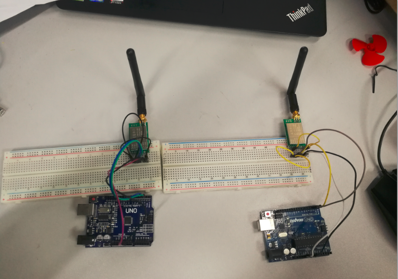
Connect two OSOYOO UART LoRa wireless modules with Arduino boards and connect them to computer via the USB cable.
| Arduino UNO |
OSOYOO UART LoRa wireless module |
| GND |
M0 |
| GND |
M1 |
| D3 |
RXD |
| D2 |
TXD |
| NC |
AUX |
| 5V |
VCC |
| GND |
GND |
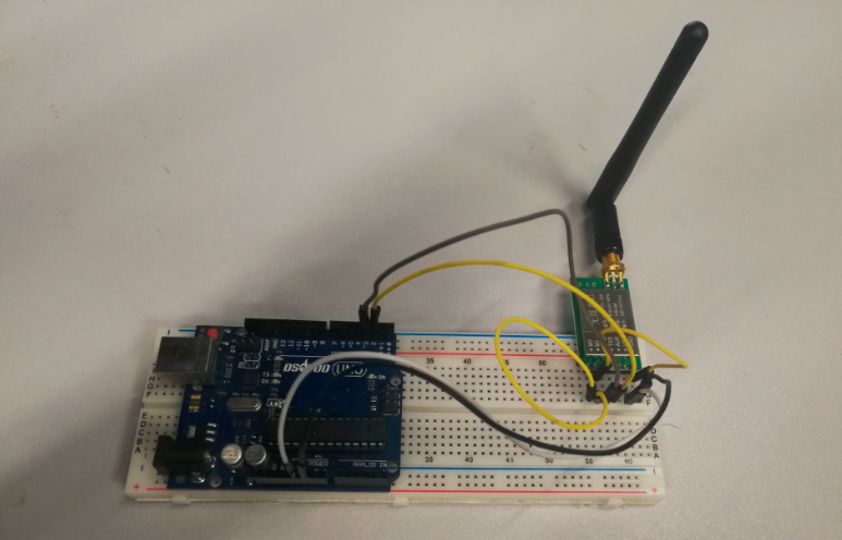
As below picture, we use the left OSOYOO UART LoRa wireless module+OSOYOO UNO as the server(device A) to transmit signal and the right one as the clien(device B)t to receive signal here.
Code Program
For Transmit and Receive, we need two Arduino IDE to run at the same time. So, we need to click the Arduino IDE’s icon for twice. Run both at the same time and copy the code to both the Arduino IDE.
#include <SoftwareSerial.h>

SoftwareSerial mySerial(2, 3); //TX, RX
// (Send and Receive)

void setup() {
  Serial.begin(9600);
  mySerial.begin(9600);
}

void loop() {


  if(Serial.available() > 0){//Read from serial monitor and send over  OSOYOO UART LoRa wireless module
    String input = Serial.readString();
    mySerial.println(input);
  }

  if(mySerial.available() > 1){//Read from  OSOYOO UART LoRa wireless module and send to serial monitor
    String input = mySerial.readString();
    Serial.println(input);
  }
  delay(20);
}
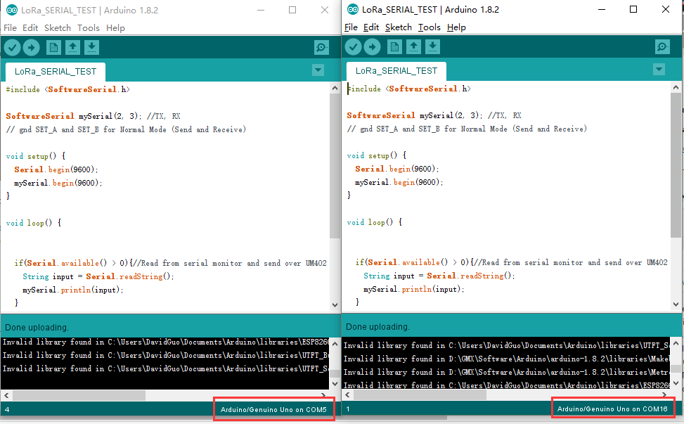
After above operations are completed, click the upload button.
Once it is done with uploading, open up the Serial Monitor at each side. Now, you can try to type some words at the Serial Monitor and wait for it to appear at another side. For example in my picture, when I type “123” in Serial Monitor COM16, it will be sent over and appear at Serial Monitor COM5.

Use the OSOYOO UART LoRa Wireless Module to Control an LED Remotely
This is an example to show how to get data from a remote Arduino via LoRa. In this case, we have two circuits. One for the transmission of data and another for reception.
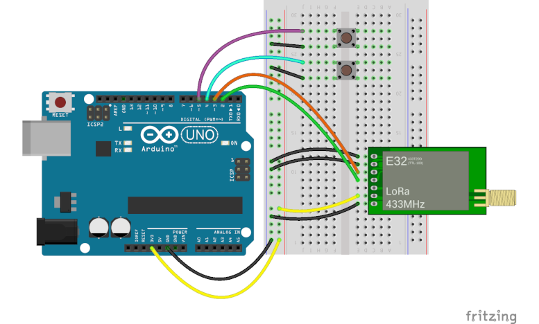
The transmission circuit
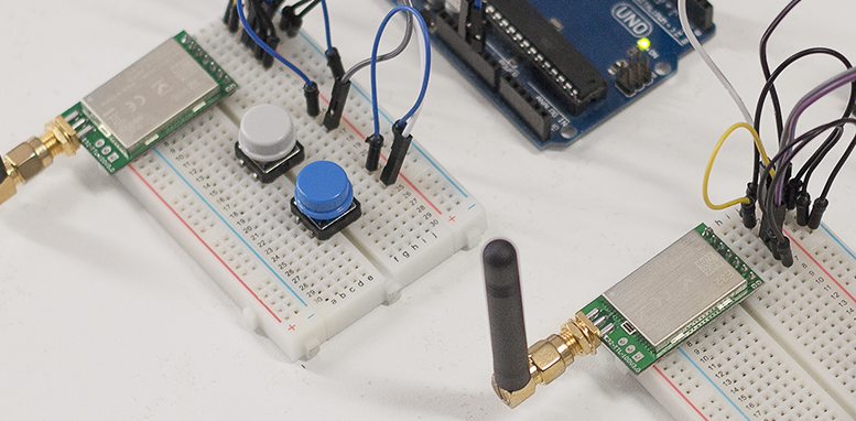
The transmission circuit consists of an Arduino, two push buttons, and the OSOYOO UART LoRa module.
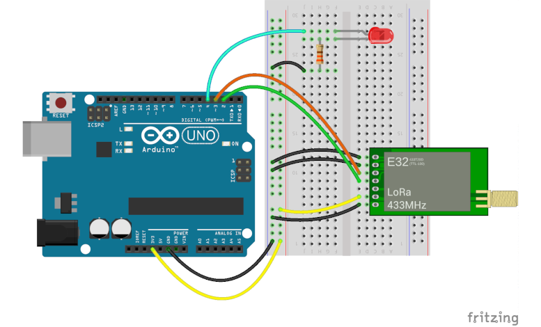
The reception circuit
The reception circuit consists of another Arduino, a LED module, resistor and another the OSOYOO UART LoRa module.
Note: Make sure you have chooes the right frequency LoRa Module for your project. Ensure that your LoRa module has an antenna with corresponding frequency.
Code Program
The code of the transmitter
The programming of the transmitter has the objective to send via protocol serial two strings “on” and “off” in accordance with each button pressed. See the code below(or download from Github):
#include <SoftwareSerial.h>

#define BTN1  4
#define BTN2  5

SoftwareSerial loraSerial(2, 3); // TX, RX

String turnOn = "on";
String turnOff = "off";


void setup() {
  pinMode(BTN1, INPUT_PULLUP);
  pinMode(BTN2, INPUT_PULLUP);
  Serial.begin(9600);
  loraSerial.begin(9600);

}

void loop() {

  if(digitalRead(BTN1) == 0) {
    loraSerial.print(turnOn);
    while(digitalRead(BTN1) == 0);
    delay(50);
  }

  if(digitalRead(BTN2) == 0) {
    loraSerial.print(turnOff);
    while(digitalRead(BTN2) == 0);
    delay(50);
  }
}
The code of the receiver
The programming of the receiver has the goal to wait for the string sent by the transmitter. When receiving the string “on” turn on the LED. When receiving the string “off” turn off the LED. See the code below(or download from Github):
#include <SoftwareSerial.h>

#define LED1  4

SoftwareSerial loraSerial(2, 3); // TX, RX

void setup() {
  pinMode(LED1, OUTPUT);
  Serial.begin(9600);
  loraSerial.begin(9600);
}

void loop() {
  if(loraSerial.available() > 1){
    String input = loraSerial.readString();
    Serial.println(input);
    if(input == "on") {
      digitalWrite(LED1, HIGH);
    }
    if(input == "off") {
      digitalWrite(LED1, LOW);
    }
  }
  delay(20);
}
Running Result

After completed above operations, push the button which is connected to D4, the LED on the receiver side will be lighted, push the button which is connected to D5, the LED on the receiver side will be put out.
Reference:
Certified Documents
Osoyoo Long Distance Wireless Transceiver Uart LoRa Module
What is LoRa Radio Network?
LoRa Architecture
LoRa Security
LoRaWAN Frequency Bands


merhaba bu çalışmanın arduino mega 2560 megaya göre kodları varmı ?
This test is based on the UNO, you can also use mega2560,Be careful when using arduino other than uno since not all pins can support SoftwareSerial!
The Module data sheet says that the “Communication level (V)” (I assume that means voltage on the TX RX pins) is maximum 3.3v otherwise you risk burning out the module yet here your example shows them connected to 5V lines without any level converters. So are the pins 5V safe despite what the data sheet says?
When using our LoRa module, we need to follow the product tutorial to connect the rx pin of the module to the tx pin of mcu, and the tx pin of the module to the rx pin of mcu
As you can see from the product datasheet, the power supply over 5v can guarantee the best performance, voltage over 5.2v may cause damage to the module, so, The power supply range is 2.3v-5.2v
The communication voltage level over 5v may at risk of burning down, the communication voltage range is 2.3-3.6v, 3.3v is the best
There, Use 5v power supply to supply power to the module, and use mcu with 3.3v level will be the best choice.
That doesn’t clarify why your example shows the module connected to 5V data lines are you saying your example is incorrect?
thanks for the article
I followed the steps, but communication takes place when the sending module is de-energized. It is really interesting as if it sends and collects packets, then when the sender closes, it prints all the packets it receives.
Can you help?
Uhm… I haven’t encountered such a situation yet. Can you describe it in more detail?
Thanks for the article. Do you have an exanple of sensor data transmission with these modules, i.e: DHT 11, GY-91?
We provide basic module usage methods and sensor usage tutorials. Wouldn’t it be more fun to make them work together?
Yes, it is exactly what I was looking for. . .A code program for trasmitting sensor data between arduinos using UART LoRa wireless module(433MHZ)…
Hi. Thanks for this afticle.
And My LoRa is LSD4WN-2L217M90 that using same chip XS1278.
The difference is that I used esp32 and version 2.3 of the arduino IDE to use SoftwareSerial.
I would appreciate it if you could let me know what else I should check.