In this experiment you will look at an example of using the accelerometer lets make a sensitive movement alarm from out micro:bit.The expanding example combining the use of the accelerometer on the micro:bit to measure the orientation of the micro:bit and use it to control the angle of a servo.
Parts Needed
You will need the following parts:
1x micro:bit
1x Micro B USB Cable
1x micro:bit Breakout (with Headers)
1x Breadboard
5x Jumper Wires
1x Servo
Introducing the Accelerometer
The accelerometer is a component that you won’t find in the kit’s bag of parts. Why? Because it is on the micro:bit itself! On the back of the micro:bit you can see a number of small chips. One of them is the accelerometer.
An accelerometer is a sensor that measures the gravitational forces pulling on it in all three dimensions of the chip’s X, Y and Z axes.
Not only can an accelerometer measure the raw forces pulling on the chip and the object that the chip is sitting on, but it can also detect steps, shakes and other motions that have a specific pattern. On top of that, you can use an accelerometer to simply detect the orientation that the device is in. Did you ever wonder how your phone knows when you turn it from portrait to landscape? It is all because of the accelerometer in your phone!
Movement Alarm Example
As an example of using the accelerometer lets make a sensitive movement alarm from out micro:bit.
The project works like this:
When you press button A, the display changes top show a triangle, indicating that the alarm will arm itself after two seconds. Once armed, the display will be blank.
If you now try and move the micro:bit then the LEDs will all light indicating that the alarm has been triggered. Put the micro:bit down, so that it’s still and then press button A to arm it again.
JavaScript Block Code
Here is the JavaScript Block version of the alarm program. The JavaScript Blocks Code editor is embedded directly on this page below. From the editor, you can click on Download button (bottom right) and then copy the downloaded file onto your micro:bit. Alternatively, you can Click here to open the editor in a separate browser tab.
The code works like this:
The on start block will be run the first time the program runs after the micro:bit has been powered-up or reset. This sets a variable z (the acceleration in the z axis) to zero. It also sets a Boolean (true or false) variable (alarm triggered) to false. The variable alarm triggered will be used to indicate to other parts of the program that the alarm has been triggered.
The forever loop will run over and over again and is in three parts, each part being an if/then block.
The first if/then block checks for a press of button A, and if button A is pressed, it displays a triangle symbol, waits two seconds (2000 milliseconds) then reads the acceleration in the z axis into the variable z. Finally it clears the screen.
The second if/then in the forever block checks the current acceleration in the z axis against the value stored in the variable z and if it is less than the stored reading by a margin of 30, it sets the variable alarm triggered to be true.
The final part of the code determines what happens when the alarm triggered variable is true. If the alarm is triggered, then the cross symbol will be shown on the display otherwise the display will be cleared. The alarm triggered variable will remain true until button A is pressed again.
MicroPython
Here is the MicroPython version of the code for the movement alarm.
from microbit import*
z =0
alarm_triggered =False
whileTrue:
if button_a.was_pressed():
# Wait for 2 seconds while the alarm is armed
display.show(Image.TRIANGLE)
sleep(2000)
z = accelerometer.get_z()# take a reading while still
alarm_triggered =False# the alarm is now armed
# Check to see if acceleration on z axis changed by 30
if accelerometer.get_z()< z –30:
alarm_triggered =True
if alarm_triggered:
display.show(Image.NO)# display a cross
else:
display.clear()
The code is almost a line by line copy of the JavaScript Blocks code, but translated into Python.
How to use the Micro bit to control the angle of a servo
Hardware Hookup
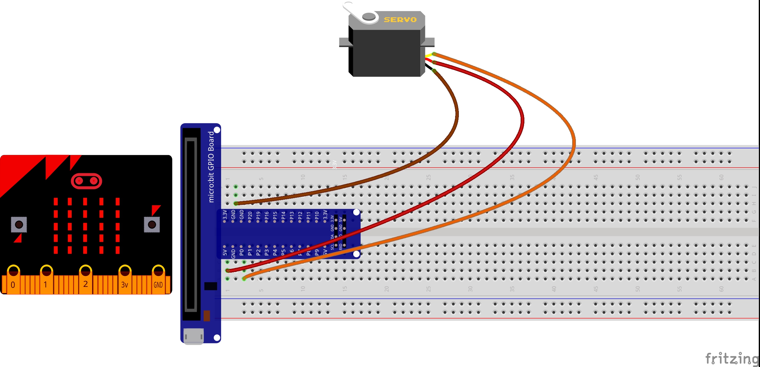
Ready to start hooking everything up? Check out the wiring diagram below to see how everything is connected.
Polarized Components
Pay special attention to the component’s markings indicating how to place it on the breadboard. Polarized components can only be connected to a circuit in one direction.
Wiring Diagram for the Experiment
Servo
Micro Bit Breakout
Brown Wire
GND
Red Wire
5v
Orange Wire
P0
Run Your Script
Either copy and paste, or re-create the following code into your own MakeCode editor by clicking the open icon in the upper right-hand corner of the editor window. You can also just download this example by clicking the download button in the lower right-hand corner of the code window.
Note: You may need to disable your ad/pop-up blocker to interact with the MakeCode programming environment and simulated circuit!
Code to Note
Let’s take a look at the code blocks in this experiment.If you are having a hard time viewing this code, click on the image above to get a better look!
Acceleration
The acceleration block can be found under the input blocks group. This block returns the force of gravity pulling on a specific axis of the micro:bit (X, Y or Z) and represents that value as a range of numbers between -1023 and 1023. In this case, we measure the X axis, which is the side-to-side tilt of the micro:bit. If you tilt the micro:bit all the way to the left, you will get a -1023 value and all the way to the right is positive 1023.
Map
The map block looks intimidating, but it is one of the most useful blocks in MakeCode. The map block takes a given variable that has a known range — in this case -1023 to 1023 — and “maps” or scales that value range to another given range. The given range we want is 15 to 165, which is a good safe range of rotation for the servo. So, in the end -1023 ends up to equal 0, and 1023 ends up as 165 from the map block.
What You Should See
At the beginning of the program the servo should move to 90 degrees and then react to the orientation of the micro:bit. If you hold the micro:bit flat, the servo will be at 90 degrees. Then if you tilt the servo to the left, it will move less than 90 degrees toward the value of 15. If you move it to the right, the servo will move toward 165.
Troubleshooting
This Seems Backward
You may be holding the micro:bit in a different orientation. Flip it around and try again!
Servo Isn’t Working
Double-check your wiring! Remember, red to 3.3 volts, black to ground, and white to signal.