In this lesson, we will show you how to make simple Internet of Things (IoT) project – to turn on/off an LED from a remote browser .
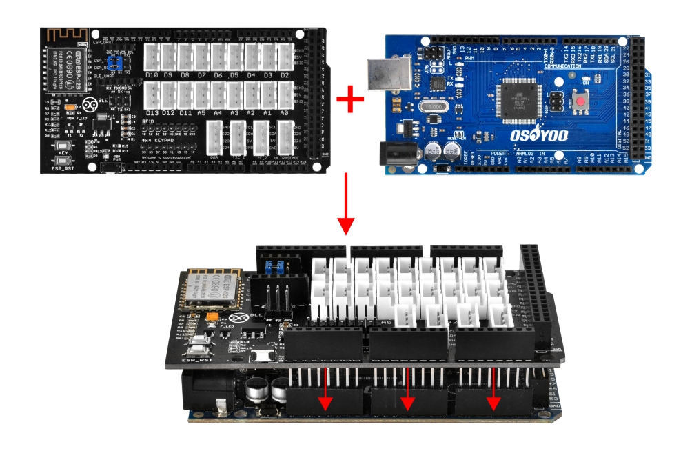
We will use Osoyoo Mega-IoT Shield to connect LED and MEGA2560 MCU board. OSOYOO Advanced Board for MEGA2560 Board can work as a web server. Remote browser can access this web server and control the LED connected to D13 pin of MEGA2560.
OSOYOO MEGA2560 Board x 1
OSOYOO MEGA-IoT Extension Board x 1
LED PnP Module x 1
OSOYOO 3-Pin PnP Cable x 1
USB Cable x 1
PC x 1
First, please plug OSOYOO MEGA-IoT Extension Board into MEGA2560 board:
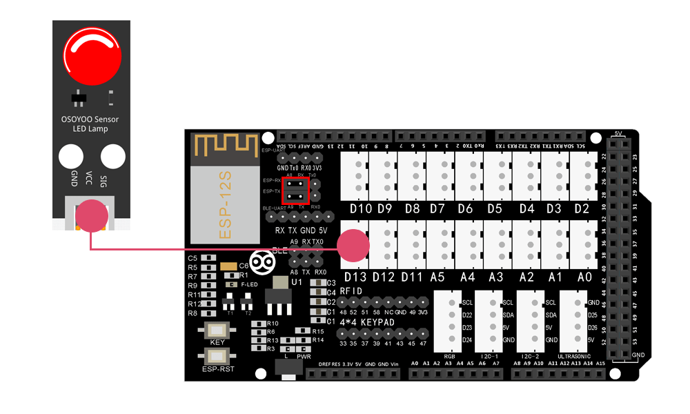
Then connect the LED module to the D13 port of the OSOYOO MEGA-IoT Extension Board with a 3-pin PnP cable as below (Jumper Cap should connect ESP8266 RX with A8, TX with A9):
Notice: Shut off your battery or Unplug your power adapter when upload sketch code to OSOYOO Advanced Board for Arduino MEGA2560.
Step 1 Install latest IDE (If you have IDE version after 1.1.16, please skip this step)
Download IDE from https://www.arduino.cc/en/software , then install the software.
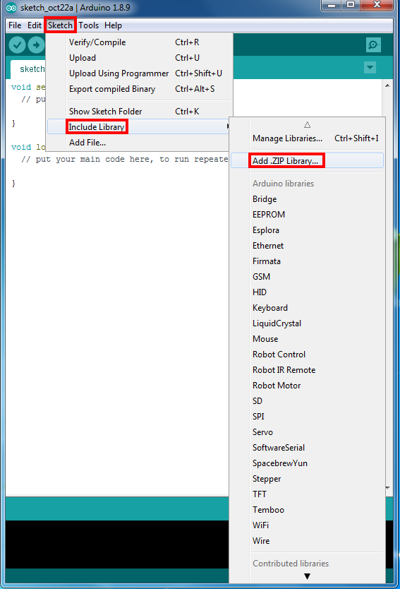
Step 2 WifiEsp Library Installation (if you have installed WifiESP library, please skip this step)
OSOYOO MEGA-IoT extension TX/RX pin to OSOYOO Advanced Board for MEGA2560 Board A9/A8 pin by default. So in sketch code, we need use Software Serial Port to communicate with ESP8266 (set A9 as TX and A8 as RX in SoftwareSerial object).
Step 4 After above operations are completed, connect the OSOYOO MEGA2560 Board to the PC with USB cable.
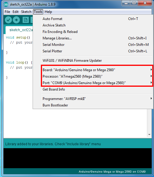
Step 5 IDE: Choose corresponding board type and port type for your project .
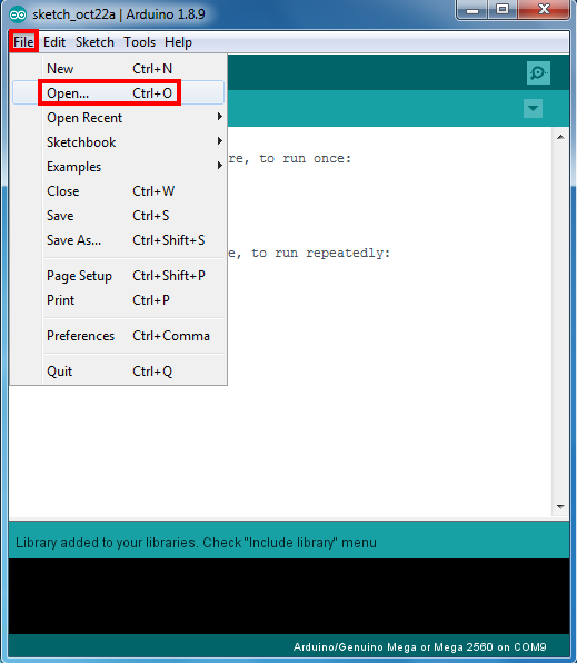
Step 6 IDE: Click file – Open, then choose code “smarthome-lesson4.ino” in the folder, load up the sketch onto OSOYOO Advanced Board for Arduino MEGA2560.
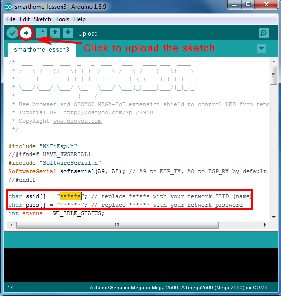
Note: In the sketch, find line 24,25 as following:
char ssid[] = "******"; // your network SSID (name)
char pass[] = "******"; // your network password
please replace the ****** with your correct wifi SSID and password, otherwise your project can not connect to Internet.
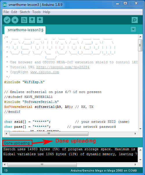
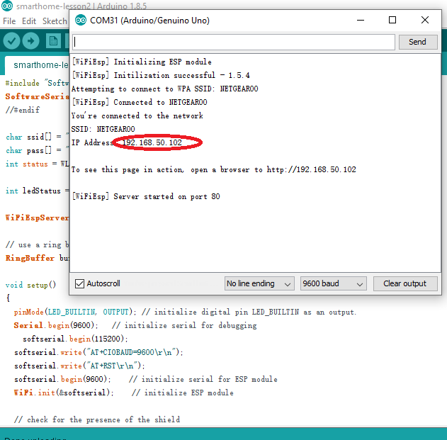
After loading the sketch to OSOYOO Advanced Board for Arduino MEGA2560 , open the serial monitor in the upper-right corner of IDE, you will see following result:
From the serial monitor, you can see the IP address of your OSOYOO Advanced Board for Arduino MEGA2560 in the read circle (in above picture, 192.168.50.102).
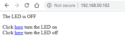
Then use your browser to visit the website http://mega2560-ip-address (in above case, http://192.168.50.102), you will see following result:
Click the two links as showed in above picture, you will turn on/off the LED module which is connected to your MEGA2560 through the IoT Shield.
I have attempted using this kit through Lesson 9 and have not been able to get any LEDs working. Lesson 3 works as expected. Lesson 4 shows the expected results on the Serial Monitor and on the generated website (including the /H and /L in the URL bar), but the LED does not light. Substituting the red LED with yellow and green also shows no light. Lesson 5 works exactly as described. Lesson 6 shows the expected results on the Serial Monitor and on the generated website, but the buzzer does not activate. Lesson 7, as far as I can tell, works as expected. I have not yet studied the code, but the values on the Serial Monitor refresh constantly, while I was expecting a refresh every 20 seconds following what was said on the generated webpage, but this might be normal. Lesson 8 shows the expected results on the Serial Monitor and on the generated website; however, while the servo operates, the LED does not. Lesson 9 may be working, but the sensor only detected fire and never showed a safe condition. Based on these results, I would suspect that the extension board is faulty. Although the instructions said that if the MEGA2650 and the extension board came as a unit, they should be left that way, I removed the extension board and a visual inspection did not show any obvious defects. I reseated the extension board on the MEGA2650 and still have the same results. The only other comment I have is that there is some personal information, i.e., SSID and password, not replaced by “*******” for, I think, Lesson 8 and Lesson 17. Well, perhaps it is not the extension board. With Lesson 4 running and measuring voltages at the LED, I get 5 VDC between VCC and ground, and when I touch the multimeter at GND and SIG, then the LED goes on. What can I do to complete these lessons? The Amazon return deadline is 11 July. Should I return this item or attempt to get an exchange?


I have attempted using this kit through Lesson 9 and have not been able to get any LEDs working. Lesson 3 works as expected. Lesson 4 shows the expected results on the Serial Monitor and on the generated website (including the /H and /L in the URL bar), but the LED does not light. Substituting the red LED with yellow and green also shows no light. Lesson 5 works exactly as described. Lesson 6 shows the expected results on the Serial Monitor and on the generated website, but the buzzer does not activate. Lesson 7, as far as I can tell, works as expected. I have not yet studied the code, but the values on the Serial Monitor refresh constantly, while I was expecting a refresh every 20 seconds following what was said on the generated webpage, but this might be normal. Lesson 8 shows the expected results on the Serial Monitor and on the generated website; however, while the servo operates, the LED does not. Lesson 9 may be working, but the sensor only detected fire and never showed a safe condition. Based on these results, I would suspect that the extension board is faulty. Although the instructions said that if the MEGA2650 and the extension board came as a unit, they should be left that way, I removed the extension board and a visual inspection did not show any obvious defects. I reseated the extension board on the MEGA2650 and still have the same results. The only other comment I have is that there is some personal information, i.e., SSID and password, not replaced by “*******” for, I think, Lesson 8 and Lesson 17. Well, perhaps it is not the extension board. With Lesson 4 running and measuring voltages at the LED, I get 5 VDC between VCC and ground, and when I touch the multimeter at GND and SIG, then the LED goes on. What can I do to complete these lessons? The Amazon return deadline is 11 July. Should I return this item or attempt to get an exchange?