Overview
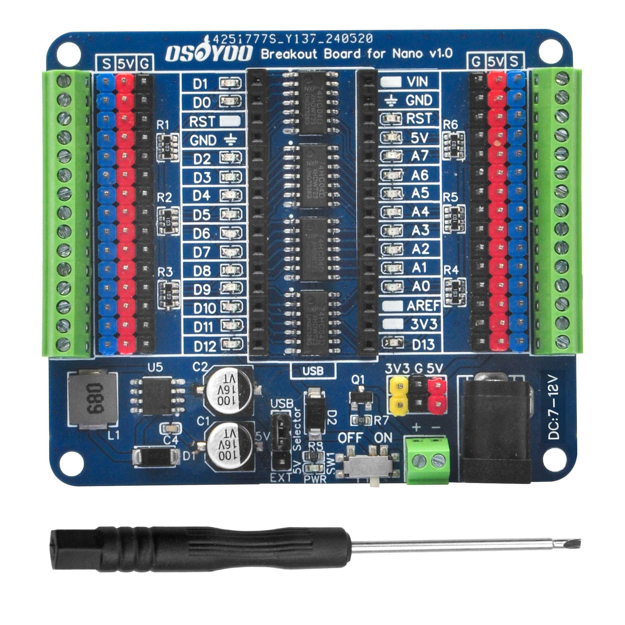
The OSOYOO Breakout Board for Nano is a circuit board designed for Arduino Nano, it adds LED indicators for each GPIO port, so you can use the indicators to know the status of the pins and easily verify your prototype code without even wiring it up.
We have added a reverse power protection circuit. When the user connects the power incorrectly, the system will automatically shut down to prevent damage to the circuit board. In addition, this break board utilizes a 3-pin interface with 5V and GND pins on each pin for easy connection to sensor modules or SG90 servos.
With on-board screw terminals for seamless compatibility and a 5V/2A independent power supply providing extra power for servos and other sensors, these practical features make it easier to bring your great ideas to life.
Compatible List
Note:
If you plan to power the board through the DC header or screw terminal port, please note that the VIN voltage for the official Arduino Nano board is 7-12V DC. If you are unsure about the VIN voltage range of your Nano board, we recommend using a voltage below 12V to avoid damaging the board or causing other risks.
Features
- Standard pin interface to achieve full compatibility with the pitch Arduino Nano and all Nano compatible boards
- LED status indicators for all GPIOs,
- Independent LED, The status LED is driven by the chip instead of the GPIO so the GPIO will not be affected.
- Terminal block and header , connect to all GPIO headers of the Nano boards, 2.54mm/0.1in pitch.
- Analog/Digital pinouts with 5V/GND
- Digital IO port 14 ports prepared to digital modules or servos
- Analog IO Port 8 ports prepared to analog sensor input
- External 5V/3.3V/GND power ports.
- Anti-reverse power screw terminals
Tech specs
| Name |
OSOYOO_IO_Breakout_Board_for_Nano_v.1.0 |
| Operating Voltage |
5V |
| Input Voltage (recommended) |
7-12V |
| Digital I/O Pins |
20 |
| PWM Digital I/O Pins |
6 |
| Analog Input Pins |
8 |
| Power Switch |
Yes |
| External Power Output |
5V/2A |
| Options for power input |
USB/DC005–2.1/Screw terminal/Male pinheads |
| On-Board LED Indicators |
All GPIO ports |
| Length |
72 mm |
| Width |
62 mm |
| Weight |
25 g |
Notes and Warnings
Diagram
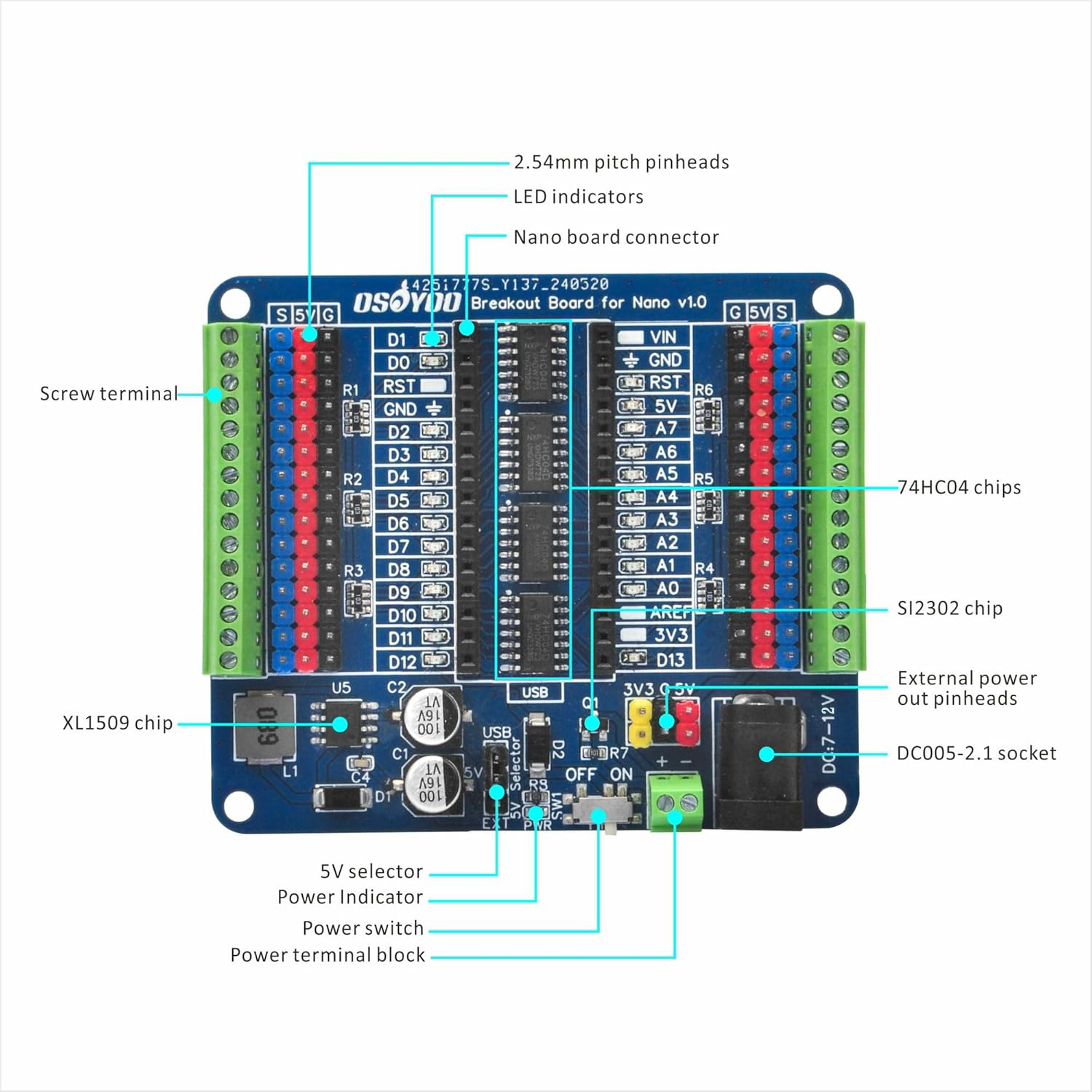
- Nano board connector: Please pay attention to the orientation of the Nano board when using it. Inserting it incorrectly or misaligning
- LED indicators: LED on if GPIO outputs/inputs high level, LED off if GPIO outputs/inputs low level.
- 2.54mm pitch pinheads: The S terminal directly connects to the Nano board, it comes with 5V and GND pins for easy connection to sensors or servos.
- Screw terminal: Connect to all GPIO headers of the Nano boards, 2.54mm/0.1in pitch
- XL1509 chip: DC/DC converter, it supports a maximum output power of 5V/2A.
- 5V selector: The jump cap is mounted on the “DC1” side by default, this means that the 5V on the I/O board comes from the Nano board, if you are using an external DC power supply through the DC header or screw terminals, you should mount the jump cap on the “EXT” side, the 5V pins on the I/O board can provide up to 2A of current.
- Power Indicator
- Power switch
- Power terminal block: We recommend using a 7-12V DC power supply.
- DC005-2.1 socket: We recommend using a 7-12V DC power supply.
- External power out pinheads: It provides additional power connections, 5V depending on how you power it and where the jump cap is on the 5v selector, and 3.3V from the Nano board.
- SI2302 chip: N-Channel MOSFET, here we use it in a power supply screw terminal anti-reverse circuit
- 74HC04 chips: It is a hex inverter. We use it to connect each I/O port to control the corresponding indicator.
Note
If you use the USB on the Nano for power supply, please do not install the jump cap to the “EXT” side, which may cause the 5v pin to be abnormally powered and the power indicator to not light up.
Do not use both the DC header and screw terminal ports for power supply, this will risk damaging the circuit board and burning out the power supply.
Assembly
When inserting, please pay attention to the boards‘ orientation,ensure the Nano board is correctly connected before applying power to the power supply interface to avoid damaging the board due to misalignment.
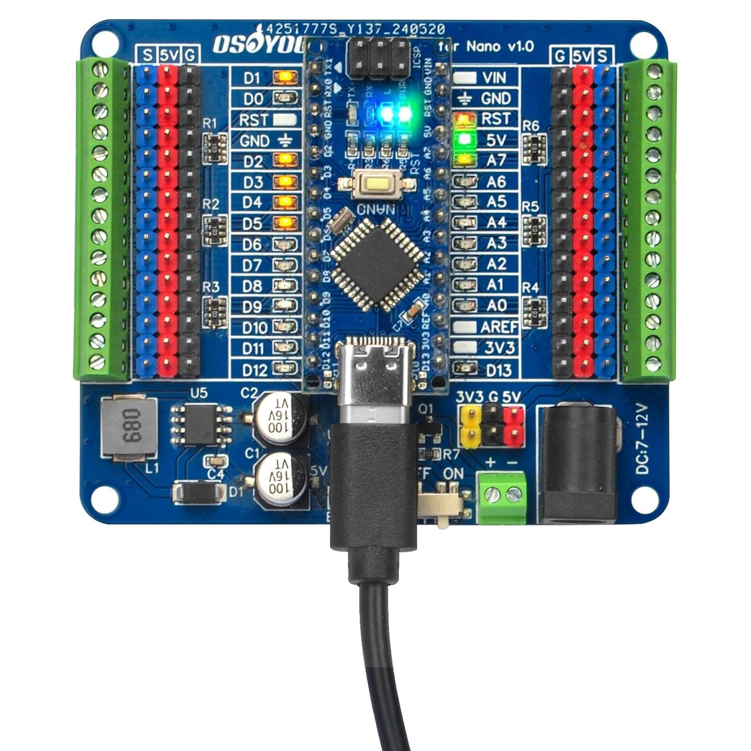
(The Nano board is not included in this product, you will need to bring your own or buy it directly from our website.)
Fritzing Part file download link:https://osoyoo.com/driver/OSOYOO_Breakout_Board_for_Nano/Fritzing-OSOYOO-Breakout-Board-for-Nano.fzz
Dimensions

DOCUMENTS
If you have any problems or difficulties using this product, please contact us for quick and free technical.


