Hardware: Raspberry Pi 3B/3B+/4B/Zero 2W
Screen: Osoyoo 3.5″ SPI Touchscreen 480×320 ( Model No.: 2022013800 )
System: This tutorial is ONLY compatible with:
• Raspberry Pi OS Bullseye (Legacy)
• Raspberry Pi OS Buster (Legacy)
NOT compatible with: Bookworm, Trixie, or any newer versions.
For Trixie setup, please refer to the separate Trixie tutorial.
Table of Contents
Getting Started
Advanced Tutorials
Reference Tutorials
Tech Support
Getting Started
A. Ready-to-use Image Installation Guide for Raspberry Pi OS
Step 1: Download Ready-to-use Image of Raspberry Pi OS from: https://osoyoo.com/driver/pi/raspberrypi.img
Step 2: Prepare a newly MicroSD memory card (TF card) with USB microSD card reader, recommend sizes are 8G, 16G, and 32G. Insert Micro SD card in USB micro SD card reader, and connect USB micro SD card reader with your PC.
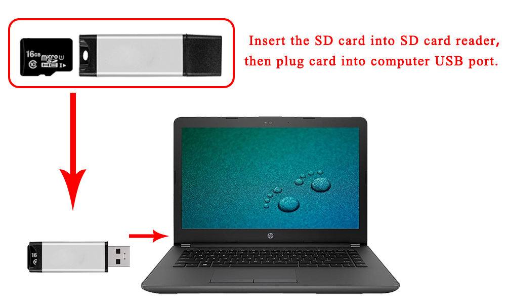
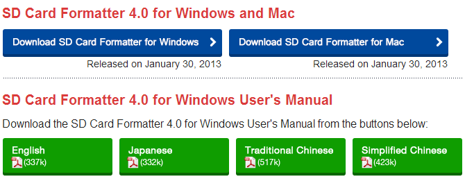
If you need to format MicroSD card, please download SDFormatter from: https://www.sdcard.org/downloads/formatter_4/.
Step 3: Download the Win32DiskImager utility from Sourceforge: https://sourceforge.net/projects/win32diskimager/
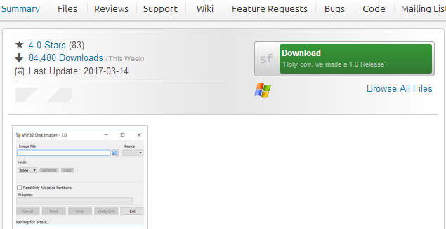
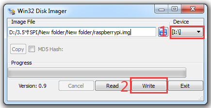
Step 4: Run the Win32DiskImager utility. You may need to run the utility as administrator. Right-click on the file, and select Run as administrator.
Step 5: Browse driver image file from Step 1:
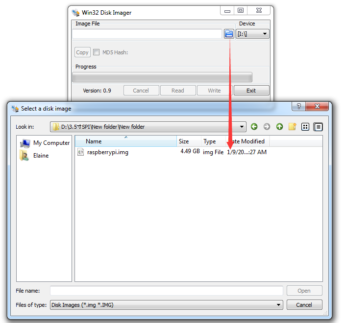
Step 6: Select correct device you prepared and click “write” to burn the driver image file (from Step 1) into MicroSD card. (Note: Please confirm you choose the correct SD card, or you’ll damage the files in your device)
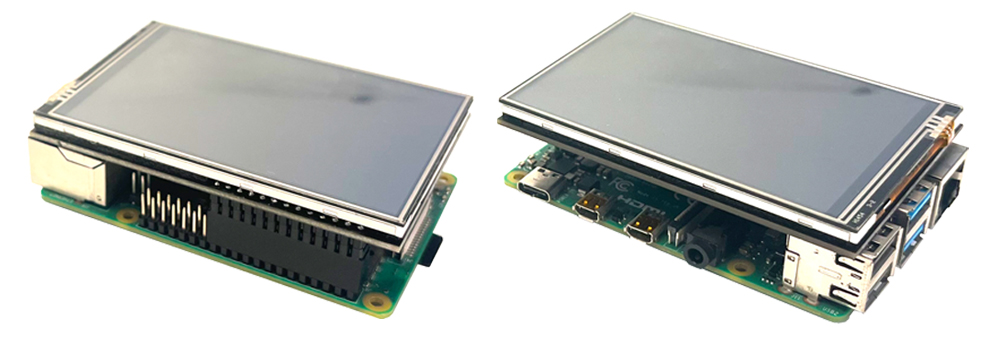
Step 7: Connecting touch screen LCD display to your Raspberry Pi (Note: There are 40 pins on Raspberry Pi, but there are 26 pins on the LCD, so you should pay attention to connecting the pins to your Pi accordingly.)
Step 8: Insert MicroSD card from step 6 into your raspberry pi and power it up.

↑ Back to Top |
Table of Contents
B. Touch Driver Installation Guide for Raspberry Pi OS
Caution:
- This tutorial is for SPI screen working with Raspberry Pi OS (Bullseye/Buster) with desktop ONLY.
- If you don’t install the touch driver and use 3.5″ SPI screen, this screen will show white screen. Please don’t worry and follow the following guide to make it work.
- You can install the touch driver on the existing Raspberry Pi OS.
- Please confirm that your SD card have enough space for touch driver.
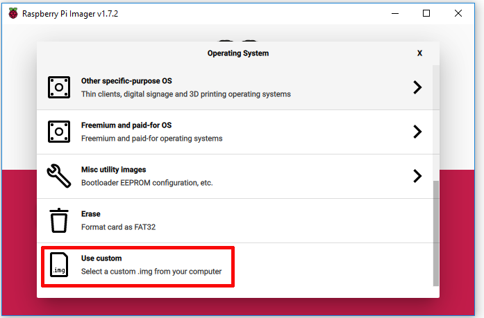
Step 1. Burn the Raspberry Pi OS (Legacy) with desktop (please download OS from Raspberry Pi official website, but don’t use BOOKWORM/Trixie Version) in a TF card/micro SD card, and insert this card in your raspberry Pi. (please confirm that the SD card have enough space for touch driver)
Note: If you use Raspberry Pi imager to burn OS, please select “use custom” to burn the Raspberry Pi OS (Legacy) with desktop you have download as following:
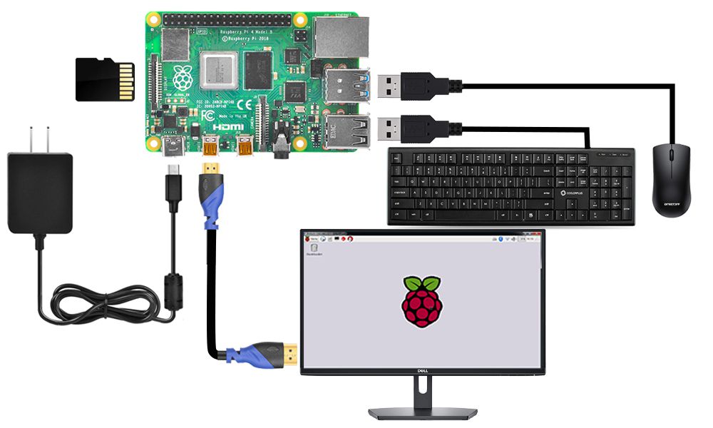
Step 2. Connect Raspberry Pi to your HDMI monitor or TV. Put a keyboard and mouse into Raspberry Pi USB ports, as following. (please don’t install 3.5″ SPI screen now, as it will show white screen)
Step 3. Getting the Raspberry Pi connected to the Internet (If you want to learn how to get the Raspberry Pi connected to the Internet, please visit https://osoyoo.com/2017/06/20/raspberry-pi-3-basic-tutorial/ )
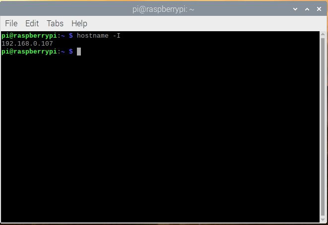
Step 4. Open terminal, and enter the following command to get the Raspberry Pi’s IP address
hostname -I
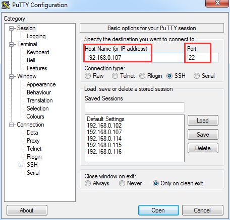
Step 5. Use ssh tool to control Raspberry Pi remotely. Here we use putty. To learn more about how to use putty to control raspberry pi remotely, please click here.
Enter the IP address you got from the last step under Host Name (or IP address) and 22 under Port (by default it is 22), then click open, then login.
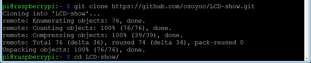
Step 6. Enter the following command in the terminal of Raspberry Pi to install the touch driver.
git clone https://github.com/osoyoo/LCD-show.git
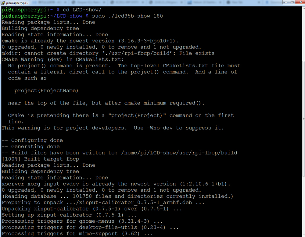
cd LCD-show/
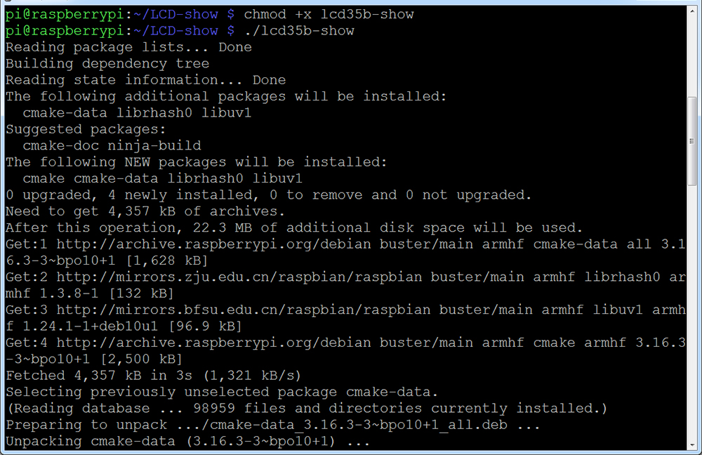
Step 7. Enter the following command in the terminal of Raspberry Pi to run touch driver
chmod +x lcd35b-show
./lcd35b-show
Wait for about 5 minutes and the touch function will restart automatically.
Step 8. Shut down and remove the HDMI/TV monitor, keyboard and mouse, then install the 3.5″ SPI screen with the Raspberry Pi which has install touch driver. (There are 40 pins on Raspberry Pi, but there are 26 pins on the LCD, so you should pay attention to connecting the pins to your Pi accordingly)
Step 9. Power on this Raspberry Pi screen.
↑ Back to Top |
Table of Contents
Advanced Tutorials
SSH Remote Control Setup
Step 1. After installing the touch driver, put a keyboard and mouse into Raspberry Pi USB ports, and open terminal, and enter the following command to get the Raspberry Pi’s IP address
hostname -I
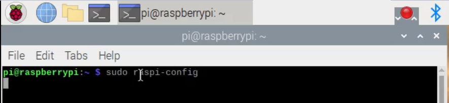
Step 2. Enter the following command to enable SSH.
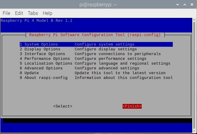
sudo raspi-config
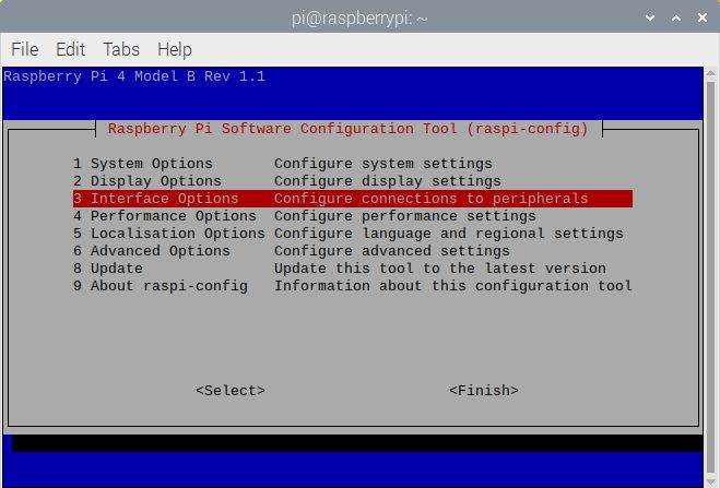
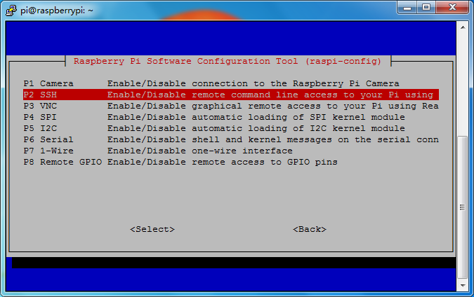
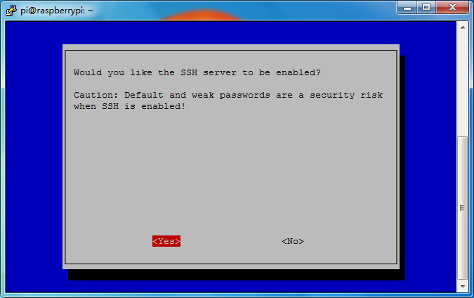
Step 3. You will go to configuration menu, select Interface Options → SSH → Yes → OK → Finish
Step 4. Install ssh tool in your computer (If you want to learn how to Use ssh tool to control Raspberry Pi’s remotely, please visit https://osoyoo.com/2017/06/20/raspberry-pi-3-basic-tutorial/)
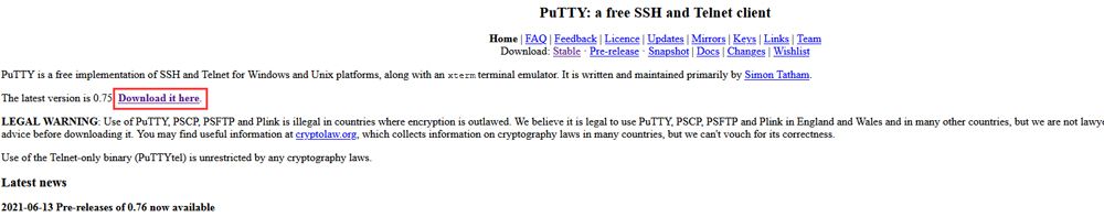
Here we take PuTTY for windows users as example. Please download PuTTY from: https://www.chiark.greenend.org.uk/~sgtatham/putty/ and install this exe. in your Windows PC
Step 5. Open PuTTY and click Session on the left tree-alike structure (generally it’s collapsed upon PuTTY startup):
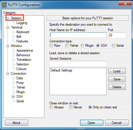
Step 6. Enter the IP address you got from step 1 under Host Name (or IP address) and 22 under Port (by default it is 22), then click open.
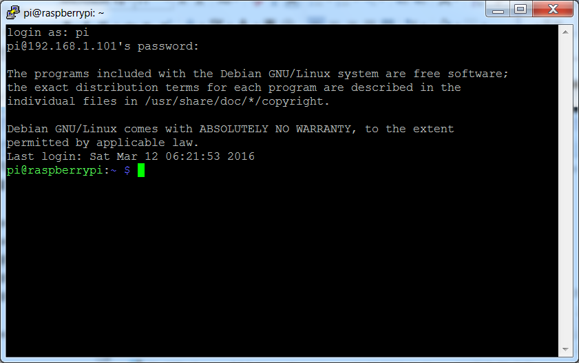
Step 7. Note that when you first log in to the Raspberry Pi with the IP address, you’ll be prompted with a security reminder. Just click Yes. When the PuTTY window prompts login as: type in the user name: pi, and password: raspberry (the default one, if you haven’t changed it).
Note: when you’re typing the password in, the window shows nothing just null, but you’re in fact is typing things in. So just focus on typing it right and press Enter. After you log in the RPi successfully, the window will display as follows:
↑ Back to Top |
Table of Contents
Rotate Display Direction
Step 1. Enter ssh tool to control Raspberry Pi remotely
Step 2. After installing the touch driver, you can rotate display clockwise by running the following commands:
Note: The rotation value can be 0, 90, 180, or 270.
This indicates that the display rotates 0, 90, 180, or 270 degrees clockwise direction, respectively.
cd LCD-show/
sudo ./lcd35b-show 90
↑ Back to Top |
Table of Contents
Install Virtual Keyboard
Step 1. Enter ssh tool to control Raspberry Pi remotely
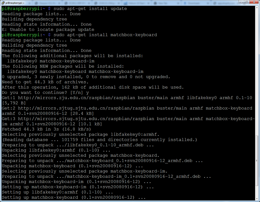
Step 2. Update and install matchbox-keyboard
sudo apt-get update
sudo apt-get install matchbox-keyboard
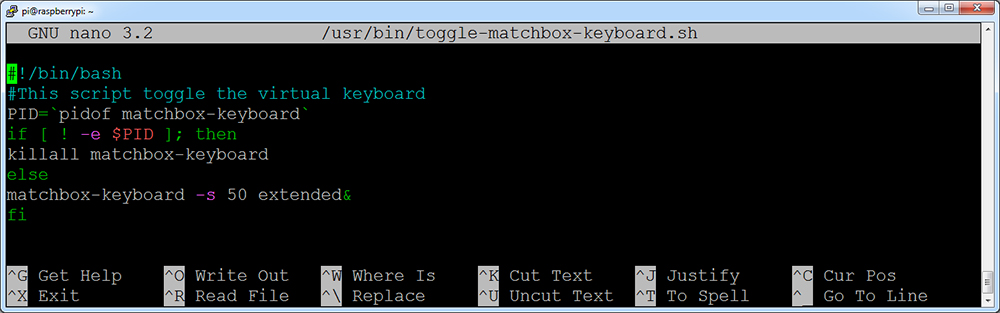
Step 3. Run the following command to create file toggle-matchbox-keyboard.sh under /usr/bin
sudo nano /usr/bin/toggle-matchbox-keyboard.sh

Step 4. Copy the statements below to toggle-matchbox-keyboard.sh and press Ctrl + X then Y to save this file, then click “Enter” to exit nano editor. (Note: press right key of keyboard to paste statements in Putty terminal).
#!/bin/bash
#This script toggle the virtual keyboard
PID=`pidof matchbox-keyboard`
if [ ! -e $PID ]; then
killall matchbox-keyboard
else
matchbox-keyboard -s 50 extended&
fi
Step 5. Execute the commands:
sudo chmod +x /usr/bin/toggle-matchbox-keyboard.sh
sudo mkdir /usr/local/share/applications

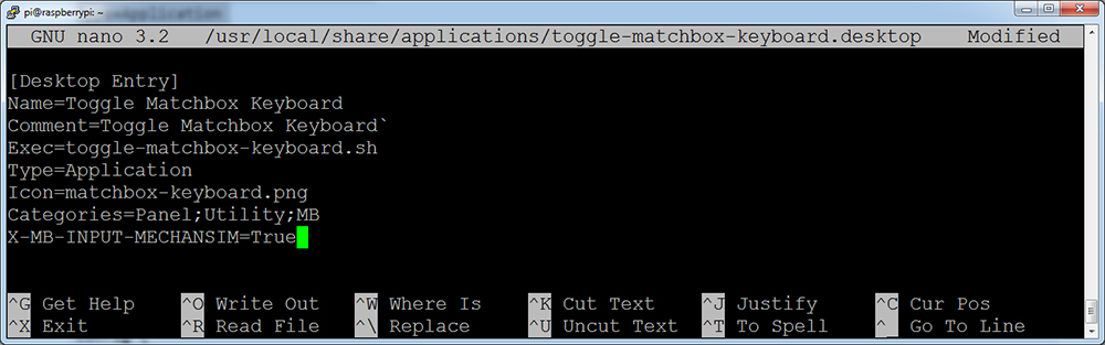
Step 6. Run the following command to create file toggle-matchbox-keyboard.desktop under /usr/local/share/applications/
sudo nano /usr/local/share/applications/toggle-matchbox-keyboard.desktop

Step 7. Copy the statements to toggle-matchbox-keyboard.desktop and press Ctrl + X then Y to save this file, then click “Enter” to exit nano editor. (Note: press right key of keyboard to paste statements in Putty terminal)
[Desktop Entry]
Name=Toggle Matchbox Keyboard
Comment=Toggle Matchbox Keyboard
Exec=toggle-matchbox-keyboard.sh
Type=Application
Icon=matchbox-keyboard.png
Categories=Panel;Utility;MB
X-MB-INPUT-MECHANSIM=True
Step 8. Execute commands as below. Note that you need to use “Pi” user permission instead of root to execute this command.
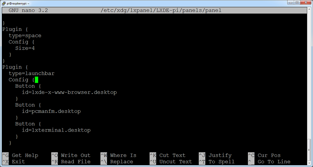
sudo nano /etc/xdg/lxpanel/LXDE-pi/panels/panel

Step 9. Find the statement which is similar to below: (It maybe different in different version. You can use Ctrl + W to search button to find this part)
Plugin {
type = launchbar
Config {
Button {
id=lxde-screenlock.desktop
}
Button {
id=lxde-logout.desktop
}
}
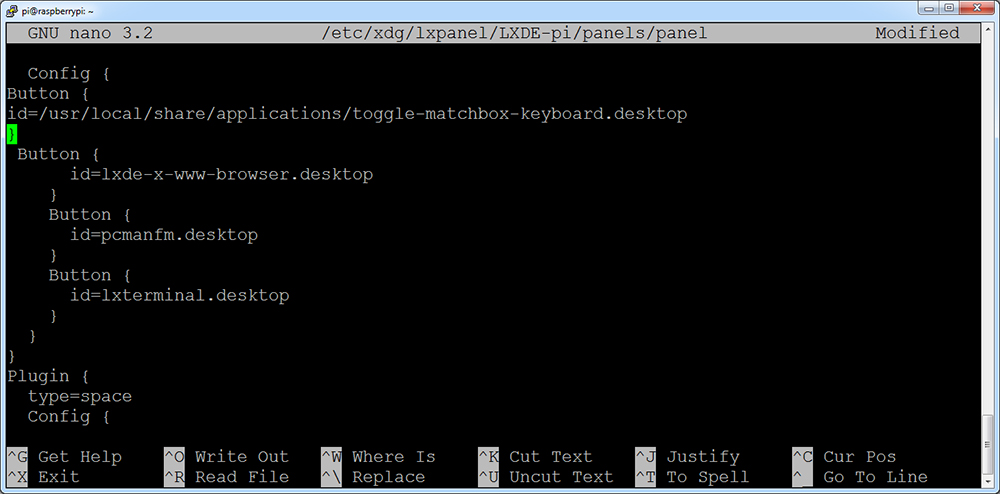
Step 10. Append these statements to add a button option, and press Ctrl + X then Y to save this file, then click “Enter” to exit nano editor. (Note: press right key of keyboard to paste statements in Putty terminal)
Button {
id=/usr/local/share/applications/toggle-matchbox-keyboard.desktop
}
Step 11. Run the following command to reboot your Raspberry Pi. If the virtual keyboard is installed correctly, you can find that there is a keyboard icon on the left of the bar
sudo reboot
↑ Back to Top |
Table of Contents
Control Backlight Brightness with GPIO
Step 1: Install WiringPi on your RPi
Make sure you have installed the wiringpi on your RPi, if not, please follow below operations:
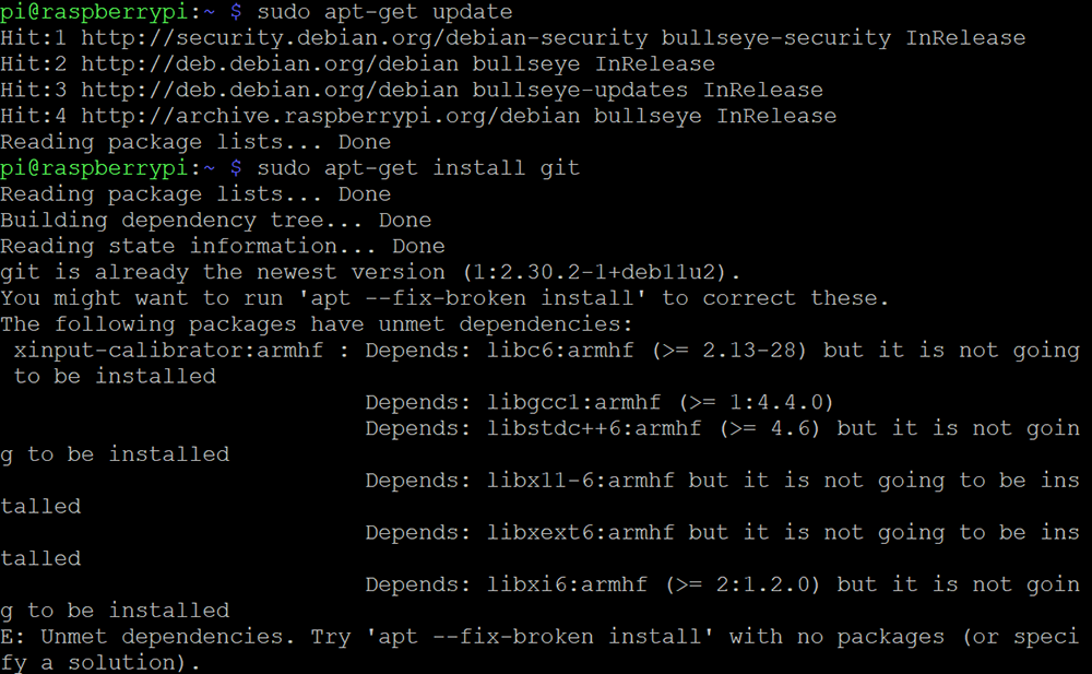
1) Run the following command to update the package list:
sudo apt-get update
2) Run the following command to install git:
sudo apt-get install git
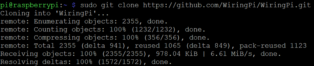
3) Run the following command to clone the wiringPi library:
sudo git clone https://github.com/WiringPi/WiringPi.git
4) Run the following command to enter the wiringPi directory:
cd WiringPi/
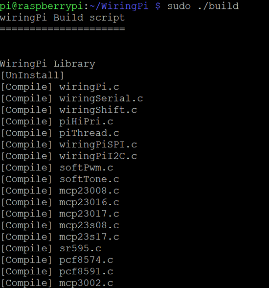
5) Run the following command to build and install wiringPi:
sudo ./build
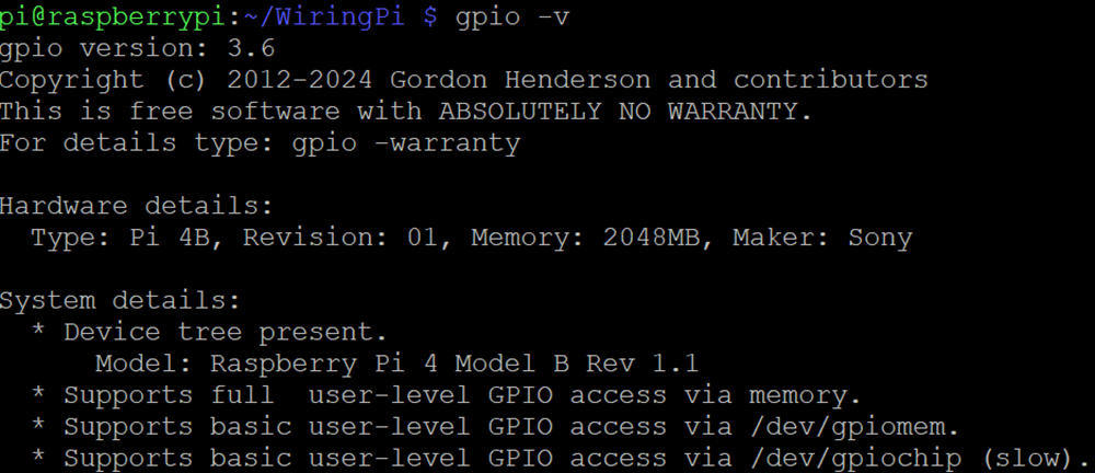
6) After the installation is complete, you can check the version of wiringPi by running the following command:
gpio -v
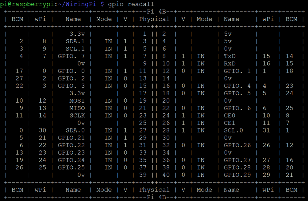
7) Check the GPIO status by running the following command:
gpio readall
Note: If you run “gpio readall” and get “Oops – unable to determine board type… model:17”, open the Raspberry Pi terminal and type:
cd /tmp
wget https://project-downloads.drogon.net/wiringpi-latest.deb
sudo dpkg -i wiringpi-latest.deb
Step 2: Backlight ON/OFF Control
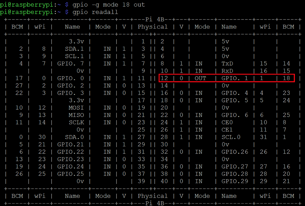
1) Set the pin mode to OUT by typing the following command:
gpio -g mode 18 out
2) Run “gpio readall” to check the status of the control pin, you should see result as following picture.
Note: 12 is physical pin number, 18 is BCM number, 1 is wiringpi number
3) Turn off the backlight by the following command:
gpio -g write 18 1
Turn on the backlight by the following command:
gpio -g write 18 0
Step 3: Adjust Backlight Brightness
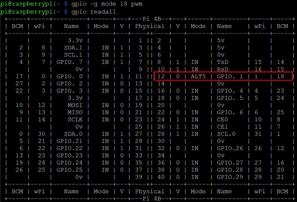
1) Set the pin to PWM mode by typing the following command:
gpio -g mode 18 pwm
2) Run “gpio readall” to check the status of the control pin, you should see result as following picture.
3) Run the following command to adjust backlight brightness:
Note: Please use a value between 0~1024 to replace X.
The larger the value, the darker the backlight (and vice versa).
gpio -g pwm 18 X

↑ Back to Top |
Table of Contents
Reference Tutorials
Choose the tutorial that matches your Raspberry Pi model and OS version:
Bookworm / Trixie RPi 4/5
Advanced • Trixie/Bookworm • 2025-10-01 and later
Advanced • Trixie/Bookworm • 2025-10-01 and later
Not sure which to choose?
• Check your Pi model: cat /proc/device-tree/model
• Check your OS version: cat /etc/os-release
Tech Support
Need help or have feedback? Submit a ticket and our team will get back to you within 1-2 working
days. We appreciate your patience!
Working Time: 9 AM – 6 PM GMT+8 (Monday – Friday)
Contact Us: [email protected]
Osoyoo 3.5″ SPI Touch Screen Setup Guide
Compatible with Raspberry Pi OS Bullseye & Buster Only
https://osoyoo.com


