Introduction
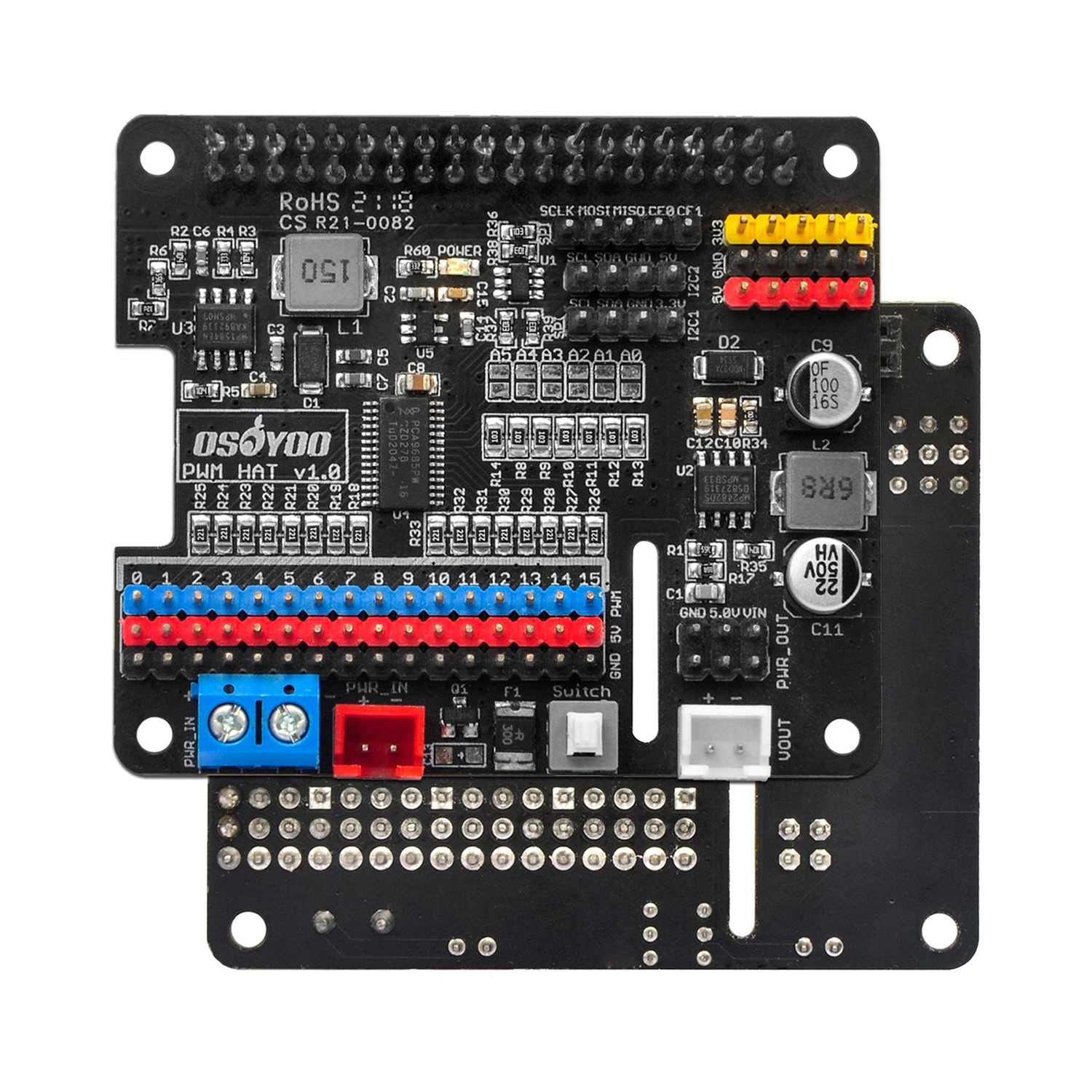
The OSOYO PWM HAT allows your Raspberry Pi to control up to 16 servo motors in a simple and straightforward manner via an I2C connection. Equally important, this expansion board integrates two power management modules, one of which provides power to the Raspberry Pi, and the other provides power to the external servos and the 5v pin on the expansion board. It is also equipped with an onboard power switch, various types of power input terminals, 3.3V/5V/VIN power supply headers, SPI interface, and two I2C interfaces for 3.3V and 5V logic level signals respectively, etc. With these, it becomes easier for you to start Raspberry Pi robotic arm and robot related projects.
These boards add the capability to control 16 Servos with perfect timing. They can also do PWM up to 1.6 KHz with 12 bit precision, all completely free-running. The OSOYOO PWM HAT will drive up to 16 servos or PWM outputs over I2C with only 2 pins. The on-board PWM controller will drive all 16 channels simultaneously with no additional Raspberry Pi processing overhead. What’s more, you can stack up to 62 of them to control up to 992 servos – all with the same 2 pins!
Works with any servo that can be powered by 5V and take 3.3V logic level signals.
Note: This plug and play HAT includes headers to connect to a Raspberry Pi, so there is no soldering required to get up and running quickly.
Features
- Power supply: 6v-18v
- Servo voltage: 5V
- Logic voltage: 3.3V
- PWM driver chip: PCA9685
- DC-DC chip for Raspberry Pi: MP1584EN
- DC-DC chip for servos&pinheads: MP2482
- Control interface: I2C
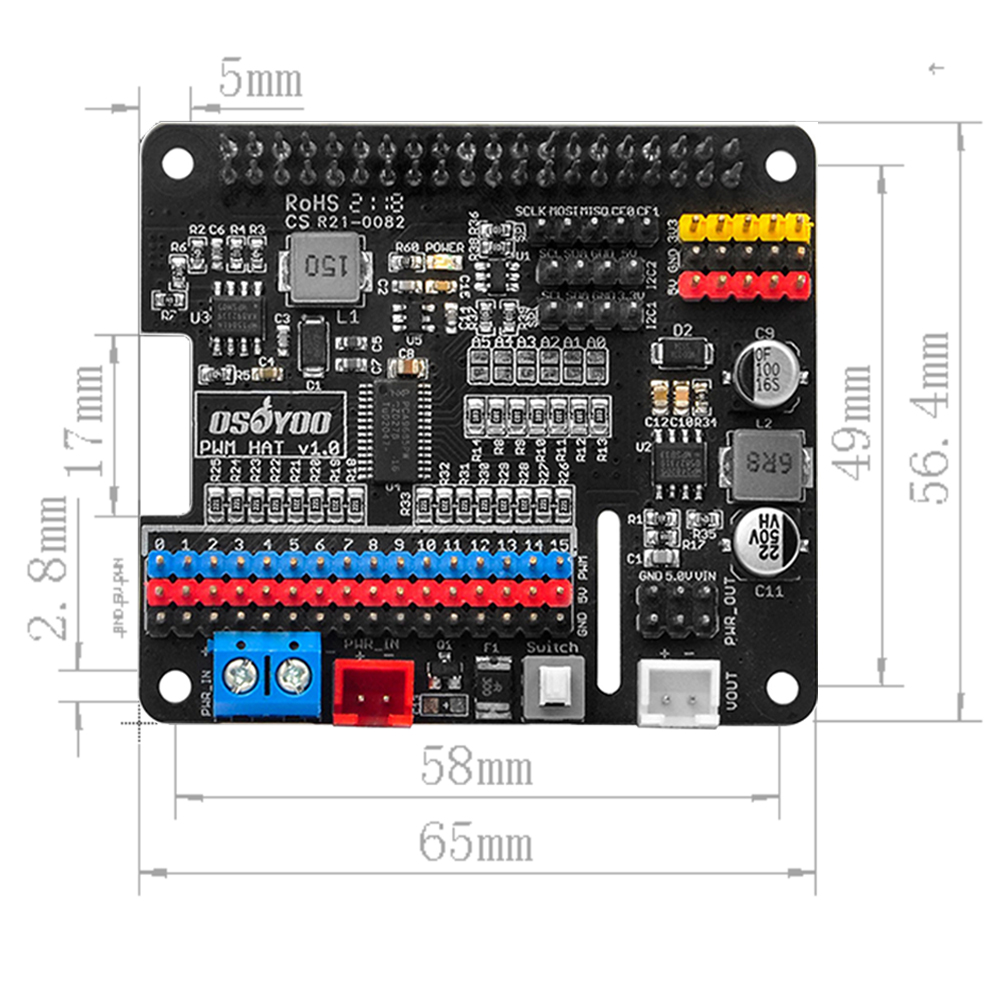
- Dimension: 65mm x 56.4mm
- Mounting hole size: 2.8mm
Hardware Description
- Standard Raspberry Pi 40PIN GPIO extension header, supports Raspberry Pi series boards, Jetson Nano, etc..
- Post screw holes: Compatible with Raspberry Pi, making the installation more secure.
- MP1584EN DC-DC chip: Power management chip for Raspberry Pi.Integrates 5V regulator, up to 3A output current, can be powered from battery through PWR_IN terminal.
- PCA9685: 16-channel, 12-bit PWM Fm+ I2C-bus LED controller. it provides I2C control over the 16-channels of 12-bit pulse width modulation (PWM) on the PWM HAT.
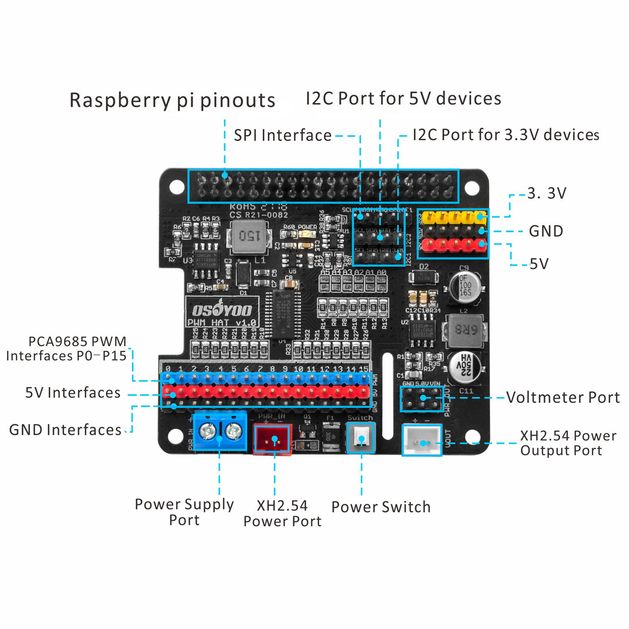
- Servo/PWM Headers: The PWM HAT can be utilized with various PWM devices, the most typically application will be servos and LEDs. These headers are spaced out to make it easier to attach servo motors to them. Additionally, they are broken out in the standard 3-pin configuration for most hobby-type servo motor connectors. The black pin headers are for GND (mostly connected to the brown wire of the servo), the red ones are for 5V power supply and the yellow ones are for PWM signal cable. There are 0-15 channels and can connect to 16 servos at the same time. Please do not connect the servo cable reversely, or the servo will not rotate.
- Screw terminal for power supply: 6V~18V DC. Do not reversely connect the polarities.
- XH2.54 terminal for power supply: 6V~18V DC.Parallel with screw terminal block. Please pay attention to the positive and negative poles of the terminal wires, do not reverse them.
- Resettable fuse: Protect the circuit in the event of excessive current.If more than 5A is drawn, it automatically throttles the current draw and/or disconnects power until the load is removed.
- Power switch: Control power on and off.
- Power output interface: The battery can be connected to other devices, controlled by the power switch.You can choose 2P XH2.54 terminal or pin headers for wiring.You can also use it as an interface for the 3-wire DC voltmeter to detect input voltage.
- MP2482EN DC-DC chip: Integrates 5V regulator, up to 5A output current.Power all onboard 5V headers, including PWM/Servo headers.
- I2C address interfaces: A0-A5 can be used to set the I2C device address of the PCA9685 chip and can be connected to multiple I2C devices to the OSOYOO PWM HAT at the same time.
- I2C_2 interface: I2C interface for 5V logic level device, the onboard logic level converter will complete the conversion of 3.3V and 5V level signals to avoid damage to the Raspberry Pi and other devices.
- I2C_1 interface: I2C interface for 3.3V logic level device,connected to the I2C interface of the Raspberry Pi directly.
- Extended power interfaces: Power supply for 3.3V and 5V devices.
- RPi SPI interface
- NDC7002N:Logic level converter.
- Power indicator
- RT9193-33: 3.3V regulator. Provide 3.3V power supply for the expansion board.
Slots are made at the DSI interface and CSI interface, which will not affect the connection to the screen or camera.
Dimensions
Applications:
-
- RGB or RGBA LED drivers
- LED status information
- LED displays
- LCD backlights
- Keypad backlights for cellular phones or handheld devices
- Servos control
- DC motors’ speed control
- etc..
Datasheet
FAQ
Can we use it with Arduino?
Absolutly! We can use the OSOYOO PWM HAT with mutiple micro control boards including Arduino. The only condition is that the main control chip supports I2C communication, which means enabling the communication between the chip and PCA9685 Servo Driver, so as to control multiple servos simultaneously.
Why do two I2C device addresses appear when scanning an I2C address?
The control chip used corresponds to PCA9685. When powered on, there are two I2C addresses, one is the address configured according to the onboard resistance, the default is 0X40, and the other is 0X70, which is configured by the ALLCALLADR register. You can run the demo again to check the value of the register.
Can two identical PWM HATs be stacked?
It can be stacked, but the resistance of the I2C address needs to be changed. In the I2C Address on the left, solder the default upper resistance to the bottom with a soldering iron. Different combinations generate different I2C address combinations, and there are a total of 62 combinations of 2 to the 5th power.
Can this HAT be used for LEDs or just servos?
It can be used for LEDs as well as any other PWM-able device! Use the Signal and Ground pins if you dont mind the LEDs powered by 3.3V and 220ohm series resistor. Or V+ and your own resistor & LED, if you want up to 5V power for the LEDs
If I’m using it with LEDs I cant quite get the PWM to be totally off?
If you want to turn the LEDs totally off use setPWM(pin, 4096, 0); not setPWM(pin, 4095, 0);
No Available Devices
Double check your connections. On a Raspberry Pi, you may get this is indicated with an OSError: [Errno 121] Remote I/O error readout.
On a Raspberry Pi, also make sure that the I2C hardware is enabled. This is usually indicated with an Error: Failed to connect to I2C bus 1. readout.
Checking Your I2C Connection
A simple method to check if your Raspberry Pi can communicate with the PWM HAT over I2C is to ping the I2C bus. On the latest releases of Raspbian Stretch, the i2ctools package should come pre-installed. If it isn’t run the following command in the terminal:
sudo apt-get install i2ctools
Once the i2ctools package is installed, you can ping the I2C bus with the following command in the terminal:
i2cdetect -y 1
You should see a table printed out in the terminal. If the PWM HAT is connected/working properly you should see the address space for 0x40 marked with 40.
Current Draw Issues
Since the Raspberry Pi provides 5V to the module by default, if the control servo power is too large (such as MG996R, DS3120MG), the 5V of the Raspberry Pi will be pulled down. If your servos are drawing more current that your power supply can handle, your Pi Servo pHAT will not operate correctly and the Raspberry Pi may reboot/brown out intermittently.
Can the angle of rotation be precisely controlled?
No, this is just entry-level.
Why does it shake?
It is normal for it to shake slightly. Since the actual angle of the servo is smaller than the minimum physical angle, there will be a current to maintain its angle, which will cause shaking.


