Introduction
The OSOYOO PWM HAT can control 16 PWM outputs via I2C communication, The two on-board voltage regulator modules provide two separate 5V power supplies for the Raspberry Pi and the servo, respectively.Among other things, it allows you to free up inputs and outputs of your microcontroller and drive up to 16 LEDs or servos (or any other module taking a PWM signal as input) using two pins (SCL and SDA) while keeping the pins of your microcontroller for other modules such as sensors. The Raspberry Pi is a microcontroller with integrated Bluetooth and Wifi modules. Very easy to use, it is lightweight and has a higher memory and computing capacity than the Arduino.
In this tutorial we will see how to use Raspberry Pi and OSOYOO PWM HAT to adjust LED brightness and drive servos.
Note: This tutorial assumes that users are familiar with the Raspberry Pi and have a general knowledge base of Python. If you have unfamiliar with these items, as a starting point, we suggest setting up your Raspberry Pi, familiarizing yourself with the graphics user interface (GUI), and then learning the basics of Python. Below are resources to get you started:
RPi Connection
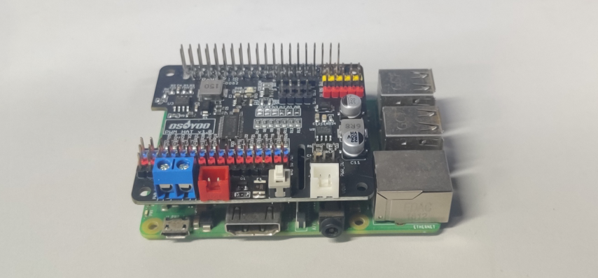
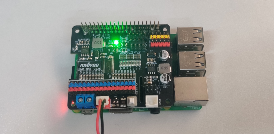
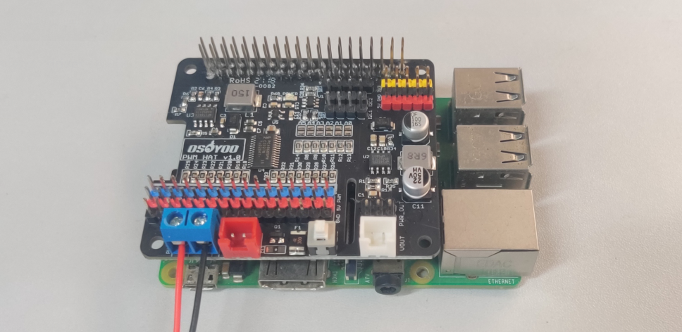
Assembling the OSOYOO PWM HAT with a Raspberry Pi is pretty straight forward. First make sure that nothing is powered. Then, just stack the board onto the Raspberry Pi so that the PCBs line up on top of each other; the HAT is NOT meant to protrude out to the side.
- Stacking the PWM HAT with the PCB protruding to the side of the Raspberry Pi instead of on top (or above) will incorrectly connect pins and will most likely damage something.
- Although usually minimal, even when connecting a Raspberry hat there is a chance to short, brown-out, and/or damage something. As a best practice, you should never plug in a hat while anything is powered (including the hat, servos, LEDs, or additional qwiic boards).
- Make sure you aren’t using a Raspberry Pi 4 or the Debian Buster image. Both have yet to be tested for use with this product.
- Never plug in a servo while your Raspberry Pi is running. The sudden current spike needed to power your servo will reset your Raspberry Pi. Always plug in all of your servos first, and then boot up.
Never plug in a servo while your Raspberry Pi is running. The sudden current spike needed to power your servo will reset your Raspberry Pi. Always plug in all of your servos first, and then boot up.
Addressing the HAT
Each HAT in the stack must be assigned a unique address. This is done with the address jumpers on the middle right of the board. The I2C base address for each board is 0x40. The binary address that you program with the address jumpers is added to the base I2C address.
To program the address offset, use a drop of solder to bridge the corresponding address jumper for each binary ‘1’ in the address.
This photo is from the Arduino Shield version of this driver but its the same setup
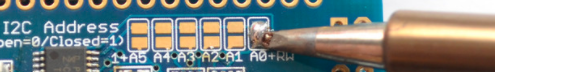
Board 0: Address = 0x40 Offset = binary 00000 (no jumpers required)
Board 1: Address = 0x41 Offset = binary 00001 (bridge A0 as in the photo above)
Board 2: Address = 0x42 Offset = binary 00010 (bridge A1)
Board 3: Address = 0x43 Offset = binary 00011 (bridge A0 & A1)
Board 4: Address = 0x44 Offset = binary 00100 (bridge A2)
etc.
Principle of operation
The module is based on the PCA9685 controller, which allows PWM outputs to be controlled using I2C communication and an integrated clock. The module has 6 bridges to select the address of the board and thus allow up to 62 controllers to be placed on the same bus for a total of 992 servomotors (addresses available 0x40 to 0x7F).
It can drive PWM outputs with adjustable frequency and 12-bit resolution. The module is compatible with 5V and 3.3V microcontrollers.
Powering Raspberry Pi / Servos
The drive integrates two power modules. One is the 5V power supply of the MP1584 voltage regulator module, which is used to power the Raspberry Pi, and the 3.3V power supply obtained by the RT9193-33 voltage regulator module is used to supply power to the PWM chip, which determines the I2C logic level and the PWM signal logic level. If the Pi is plugged in, power to the Raspberry Pi is controlled by the HAT’s onboard power switch, check the PWR LED on the Pi (it’s the red LED on the Pi 2, 3, 4. Pi Zero doesn’t have a PWR LED, look for a blinking Activity LED )
Another MP2482EN module supplies power to the steering gear and the onboard 5V pin header, and the power supply connected to the onboard power interface supplies power to both modules at the same time.
Connect to the 2P XH2.54 power socket
Connect to the screw terminals
You can connect this power supply through junction box or 2P XH2.54 DC interface, this power supply should be 6~18VDC. There is reverse polarity protection if you connect the power supply backwards, but you should use either the 2P XH2.54 DC socket or the terminal blocks, not both! (If you’re lighting a single 20mA standard draw LED, you can use the Raspberry Pi USB for power, but I’m assuming you want to use a servo here.)
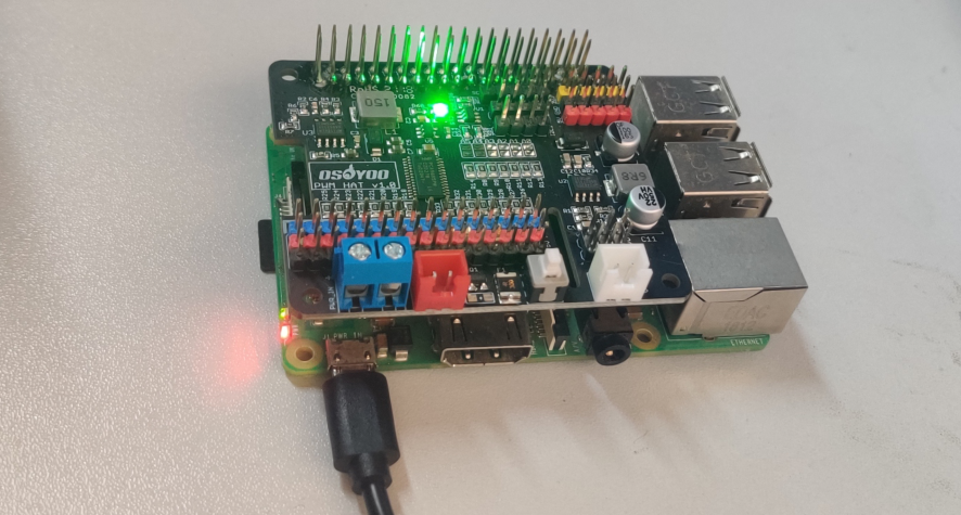
Powered by USB adapter
Note: If you just connect the Raspberry Pi USB power port, the Raspberry Pi and PCA99685 and the 3.3V pin header will work normally, but the servo power and 5V pins on the HAT will not work. Please do not use the Raspberry Pi USB port and the HAT power port for power supply at the same time!
Current Draw Requirements
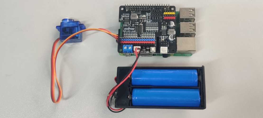
Almost all servos are designed to run on around 5 or 6v. Keep in mind that many servos moving simultaneously (especially large and powerful ones) will require a lot of current. Even tiny servos draw hundreds of milliamps while moving. Some high torque servos can draw over 1A under load.
Here we will use two 18650 batteries to power them. Of course, you can also choose other battery combinations over 6V, or directly use a 6-18V DC power adapter to provide power through the terminals.
SAFETY CAUTIONS
- Li-ion and Li-po batteries are quite unstable. They may cause fire, personal injury, or property damage, if they’re not properly recharged or used.
- Do not reversely connect the polarities when recharging or discharging the battery. Do not use inferior charger/charging panel to recharge the battery.
- Do not mix use old batteries with new ones, avoid using batteries of different brands.
- When buying Lithium battery, should always make sure the battery specification is compatible with the expansion board. Choose batteries from formal manufacturer, and ensure the batteries will work stably and safely by aging test.
- Lithium batteries have limited cycle life, they will also deteriorate as time goes by. Should be replaced with new ones when the batteries reaching their max cycle life, or working over two years, whichever comes first.
- Should be placed carefully and properly, keep it away from inflammables and explosives articles, away from children, avoid any safety accident caused by careless storage.
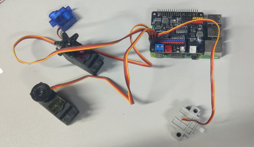
Connecting a Servo
Most servos come with a standard 3-pin female connector that will plug directly into the headers on the Servo HAT headers. Be sure to align the plug with the ground wire (usually black or brown) with the bottom row and the signal wire (usually yellow or white) on the top.
Works with any servo that can be powered by 5V and take 3.3V logic level signals.
Adding More Servos
Up to 16 servos can be attached to one board. If you need to control more than 16 servos, additional boards can be stacked as described on the next page.
Install and test PWM HAT with LEDs
Step 1 – Plug in HAT
Begin by having the Pi shutdown and not powered, plug the HAT on top to match the 2×20 headers, and power up the Pi.
Please use sudo raspi-config command to enable I2C before you using this board
Check I2C address by following command:
sudo i2cdetect -y 1
This will search /dev/i2c-1 for all address, and if an Adafruit PWM/Servo HAT is properly connected and it’s set to its default address — meaning none of the 6 address solder jumpers at the top of the board have been soldered shut — it should show up at 0x40 (binary 1000000) as follows:
Once both of these packages have been installed, and i2cdetect finds the 0x40 I2C address, you have everything you need to get started accessing I2C and SMBus devices in Python.
It’s easy to control PWM or servos with the OSOYOO PWM HAT. Install servo libraries by following two commands:
sudo pip install  --break-system-packages adafruit-circuitpython-pca9685
sudo pip install  --break-system-packages adafruit-circuitpython-servokit
Above libraries make it easy to write Python code to control PWM and servo motors.
Python Wiring
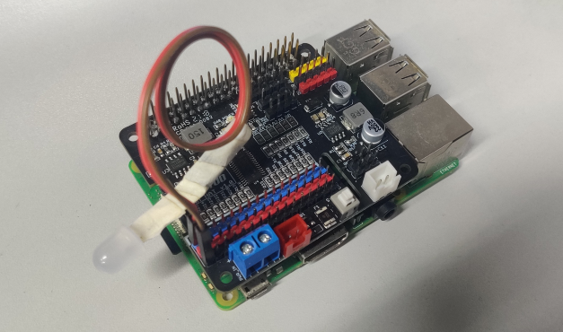
First assemble the HAT exactly as shown in the previous pages. There’s no wiring needed to connect the HAT to the Pi. The example below shows the HAT attached to a Pi.
To dim an LED, wire it to the board as follows. Note: you don’t need to use a resistor to limit current through the LED as the HAT will limit the current to around 10mA.
- Connect LED cathode / shorter leg to HAT channel GND / ground.
- Connect LED anode / longer leg to HAT channel PWM.
External power is not necessary to PWM an LED.
To control a servo, wire it to the board as shown in the previous pages, including a barrel jack to the power terminal to attach an appropriate external power source to the HAT. The HAT will not power servos without an external power source!
Dimming LEDs
Connect an LED to PCA9685 port 15
Sample Code:
import time
from gpiozero import OutputDevice
from board import SCL, SDA
import busio
from adafruit_pca9685 import PCA9685
# Create the I2C bus interface.
i2c_bus = busio.I2C(SCL, SDA)
pwm =  PCA9685(i2c_bus)
pwm.frequency = 50
LED =15 #LED connects to PCA9685 port 15
# Increase brightness:
for i in range(0xffff):
pwm.channels[LED].duty_cycle = i
# Decrease brightness:
for i in range(0xffff, 0, -1):
    pwm.channels[LED].duty_cycle = i
For dimming LEDs you typically don’t need to use a fast PWM signal frequency and can set the board’s PWM frequency to 60hz by setting the frequency attribute:
The HAT support 16 separate channels that share a frequency but can have independent duty cycles. That way you could dim 16 LEDs separately!
These for loops take a while because 16-bits is a lot of numbers. CTRL-C to stop the loop from running and return to the REPL.
That’s all there is to dimming LEDs using CircuitPython and the PWM HAT!
Controlling Servos
Connect a SG90 servo in pwm 0 port :
Sample Code testservo.py:
import time
import RPi.GPIO as GPIO
# Import the PCA9685 module.
from board import SCL, SDA
import busio
# Import the PCA9685 module.
from adafruit_pca9685 import PCA9685
from adafruit_servokit import ServoKit
kit = ServoKit(channels=16)
servo_lft = 135 #ultrasonic sensor facing 45 degree left
servo_ctr = 90 #ultrasonic sensor facing front
servo_rgt = 45 #ultrasonic sensor facing 135 degree right

kit.servo[0].angle = servo_lft
time.sleep(1)
print("facing right")
kit.servo[0].angle = servo_rgt
time.sleep(1)
print("facing center")
kit.servo[0].angle = servo_ctr
time.sleep(3)
Now you’re ready to control both standard and continuous rotation servos.
Run
python testservo.py
The servo will rotate from left to right and then stop in the center
That’s all there is to controlling continuous rotation servos with the PWM HAT, Python and ServoKit!
Full Example Code
"""Simple test for a standard servo on channel 0 and a continuous rotation servo on channel 1."""
import time
from adafruit_servokit import ServoKit
kit = ServoKit(channels=8)
kit.servo[0].angle = 180
kit.continuous_servo[1].throttle = 1
time.sleep(1)
kit.continuous_servo[1].throttle = -1
time.sleep(1)
kit.servo[0].angle = 0
kit.continuous_servo[1].throttle = 0
Click below link for Library Reference
Datasheet
FAQ
Can we use it with Arduino?
Absolutly! We can use the OSOYOO PWM HAT with mutiple micro control boards including Arduino. The only condition is that the main control chip supports I2C communication, which means enabling the communication between the chip and PCA9685 Servo Driver, so as to control multiple servos simultaneously.
Why do two I2C device addresses appear when scanning an I2C address?
The control chip used corresponds to PCA9685. When powered on, there are two I2C addresses, one is the address configured according to the onboard resistance, the default is 0X40, and the other is 0X70, which is configured by the ALLCALLADR register. You can run the demo again to check the value of the register.
Can two identical PWM HATs be stacked?
It can be stacked, but the resistance of the I2C address needs to be changed. In the I2C Address on the left, solder the default upper resistance to the bottom with a soldering iron. Different combinations generate different I2C address combinations, and there are a total of 62 combinations of 2 to the 5th power.
Can this HAT be used for LEDs or just servos?
It can be used for LEDs as well as any other PWM-able device! Use the Signal and Ground pins if you dont mind the LEDs powered by 3.3V and 220ohm series resistor. Or V+ and your own resistor & LED, if you want up to 5V power for the LEDs
If I’m using it with LEDs I cant quite get the PWM to be totally off?
If you want to turn the LEDs totally off use setPWM(pin, 4096, 0); not setPWM(pin, 4095, 0);
No Available Devices
Double check your connections. On a Raspberry Pi, you may get this is indicated with an OSError: [Errno 121] Remote I/O error readout.
On a Raspberry Pi, also make sure that the I2C hardware is enabled. This is usually indicated with an Error: Failed to connect to I2C bus 1. readout.
Checking Your I2C Connection
A simple method to check if your Raspberry Pi can communicate with the PWM HAT over I2C is to ping the I2C bus. On the latest releases of Raspbian Stretch, the i2ctools package should come pre-installed. If it isn’t run the following command in the terminal:
sudo apt-get install i2ctools
Once the i2ctools package is installed, you can ping the I2C bus with the following command in the terminal:
i2cdetect -y 1
You should see a table printed out in the terminal. If the PWM HAT is connected/working properly you should see the address space for 0x40 marked with 40.
Current Draw Issues
Since the Raspberry Pi provides 5V to the module by default, if the control servo power is too large (such as MG996R, DS3120MG), the 5V of the Raspberry Pi will be pulled down. If your servos are drawing more current that your power supply can handle, your Pi Servo pHAT will not operate correctly and the Raspberry Pi may reboot/brown out intermittently.
Can the angle of rotation be precisely controlled?
No, this is just entry-level.
Why does it shake?
It is normal for it to shake slightly. Since the actual angle of the servo is smaller than the minimum physical angle, there will be a current to maintain its angle, which will cause shaking.