Table of Contents
⚠ Compatibility Notice — Please Read Before Purchase
This breakout board is compatible with most 30-pin ESP32-WROOM, ESP32-WROVER, and 30-pin ESP8266 NodeMCU development boards ONLY.
It is NOT compatible with any boards in the following ESP32 series:
• ESP32-P series (e.g. ESP32-P4)
• ESP32-S series (e.g. ESP32-S2, ESP32-S3)
• ESP32-C series (e.g. ESP32-C3, ESP32-C6)
• ESP32-H series (e.g. ESP32-H2)
Before purchasing, please verify the following about your development board:
1. Chip model — must be ESP32-WROOM, ESP32-WROVER, or ESP8266
2. Pin count — must be exactly 30 pins
3. Pin layout — must match the standard 30-pin WROOM / WROVER or ESP8266 NodeMCU pinout
Compatibility Table
| Development Board |
Compatible |
| ESP32-WROOM (30-pin dev board) |
✓ Yes |
| ESP32-WROVER (30-pin dev board) |
✓ Yes |
| ESP8266 NodeMCU (30-pin) |
✓ Yes |
| ESP32-P series (e.g. ESP32-P4) |
✗ No |
| ESP32-S series (e.g. ESP32-S2, S3) |
✗ No |
| ESP32-C series (e.g. ESP32-C3, C6) |
✗ No |
| ESP32-H series (e.g. ESP32-H2) |
✗ No |
| Any non-30-pin board |
✗ No |
1. Overview
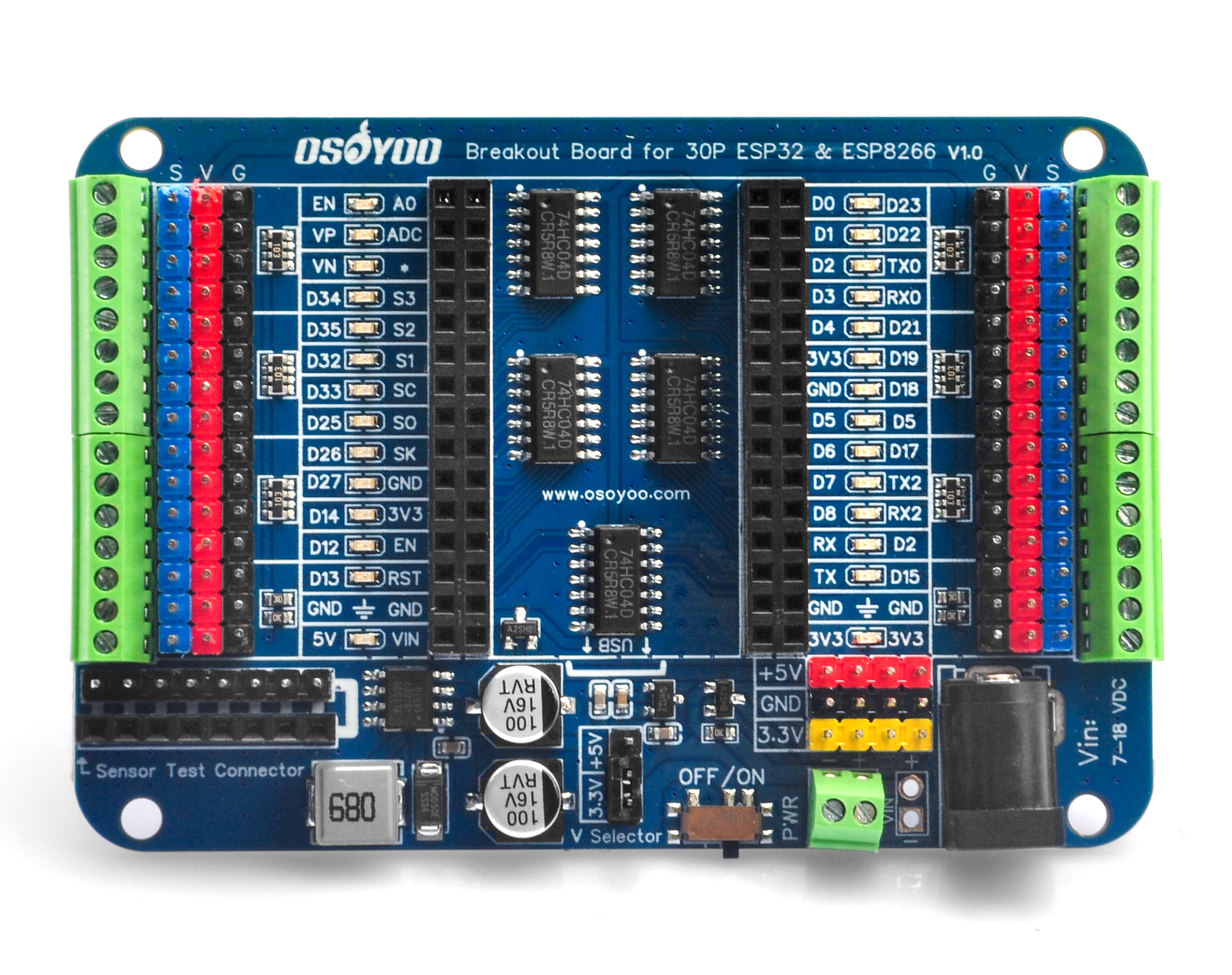
The OSOYOO Breakout Board is a versatile and user-friendly expansion board tailored for ESP32-WROOM, ESP32-WROVER, and ESP8266 modules with 30-pin headers. It is designed for both beginners and experienced developers, suitable for educational projects, prototyping, and advanced development.
The board features two sets of 2×15-pin row connectors, supporting pin spacings of 0.9 / 1.0 / 1.1 inches (22.86 / 25.4 / 27.94 mm), accommodating most standard 30-pin modules.
A separate 38-pin variant is available for users requiring a different configuration: OSOYOO Breakout Board for 38-Pin ESP32
2. Features
- LED Status Indicators: Each GPIO port has an LED indicator displaying the high/low state of the pin. LEDs are driven by an onboard 74HC04 chip — not by the ESP32/ESP8266 GPIO directly — so GPIO functionality and current output are not affected.
- Reverse Polarity Protection: An onboard reverse power protection circuit (SI2302 N-Channel MOSFET) prevents damage if power is connected with incorrect polarity.
- Dual Power Output: Provides 5V/2A (via XL1509 DC/DC converter) and 3.3V/500mA (via LDO regulator), with automatic switching between USB and external power sources.
- Voltage Selector: A V_Selector jumper lets you choose between 3.3V and 5V for the V output pin. Default is 3.3V. Always verify this setting before connecting peripherals.
- Dual Connection Options: Both 2.54mm pitch pin headers and screw terminals are available for connecting sensors, servos, and other peripherals.
- Onboard Power Switch: A dedicated power switch allows easy control of board power without unplugging cables.
- Wide Module Compatibility: Supports pin spacings of 0.9 / 1.0 / 1.1 inches, accommodating most standard 30-pin ESP32-WROOM, ESP32-WROVER, and ESP8266 NodeMCU modules.
3. Specification
| Item |
Detail |
| Model |
OSOYOO_IO_Breakout_Board_for_30P_ESP32 & ESP8266_v1.0 |
| Operating Voltage |
5V |
| VIN Input (Recommended) |
7–12V DC |
| VIN Input (Maximum) |
7–18V DC |
| External Power Output |
5V / 2A & 3.3V / 500mA |
| ADC Channels |
18 |
| PWM Digital I/O Pins |
16 |
| Pin Count |
30 |
| Onboard LED Indicators |
28 |
| Power Switch |
Yes |
| Dimensions |
88 mm x 60 mm |
| Weight |
45 g |
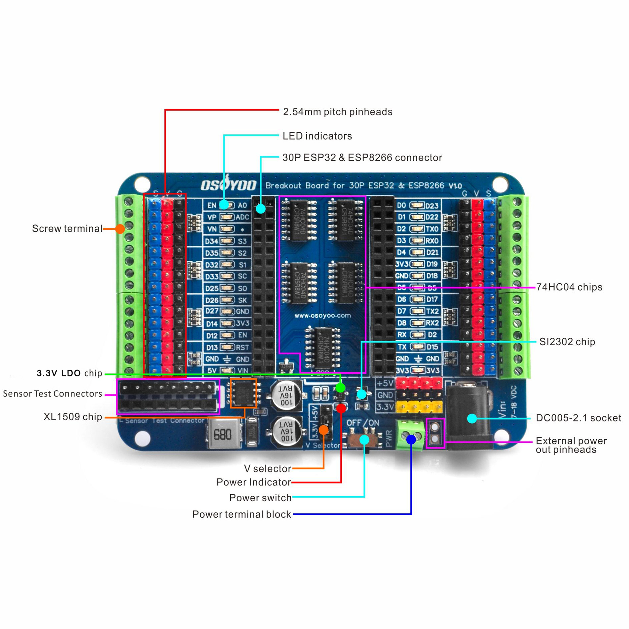
4. Board Component Description
| No. |
Component |
Description |
| 1 |
30P Connector |
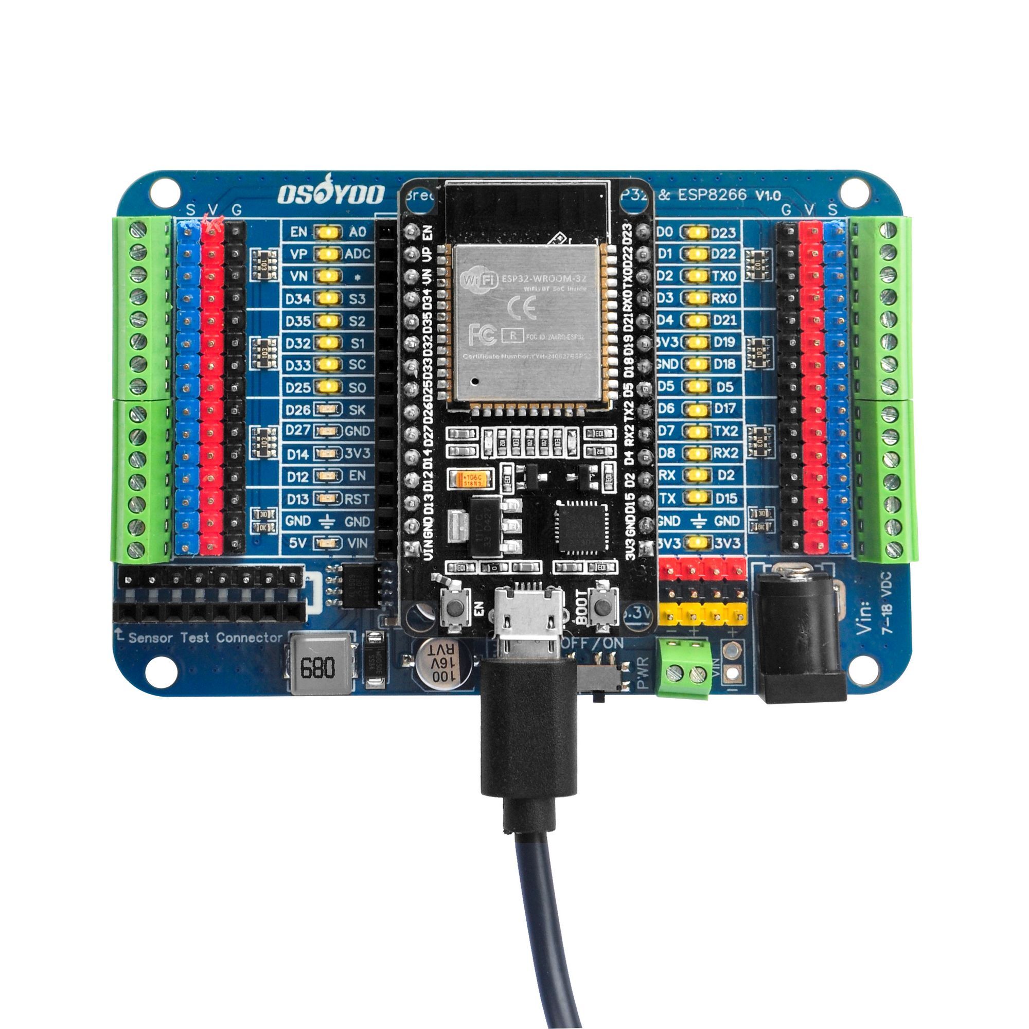
Two 2×15-pin headers for mounting the ESP32/ESP8266 module. Ensure correct orientation before applying power. |
| 2 |
LED Indicators |
Light up when corresponding GPIO pins are HIGH. Driven by onboard chip, not GPIO directly. |
| 3 |
2.54mm Pin Headers |
Direct GPIO access pins with V and GND pins included. |
| 4 |
Screw Terminals |
Screw-type GPIO connections for secure wiring of sensors and peripherals. |
| 5 |
XL1509 Chip |
DC/DC converter providing stable 5V / 2A output. |
| 6 |
LDO Chip |
Low-dropout regulator providing 3.3V / 500mA output. |
| 7 |
V Selector Jumper |
Switch V output pin between 3.3V (default) and 5V. |
| 8 |
Power Switch |
Onboard master power control switch. |
| 9 |
Power Terminal Block |
Screw terminal for 7–12V DC external power input. |
| 10 |
DC005-2.1 Socket |
Barrel jack for 7–12V DC external power input. |
| 11 |
External Power Pin Headers |
Pins for connecting external power supply or powering external devices. |
| 12 |
SI2302 Chip |
N-Channel MOSFET providing reverse polarity protection. |
| 13 |
74HC04 Chips |
Hex inverter ICs driving the LED indicators independently from GPIO. |
| 14 |
Sensor Test Connectors |
8-pin male and female connectors for sensor testing. |
5. Dimensional Drawing
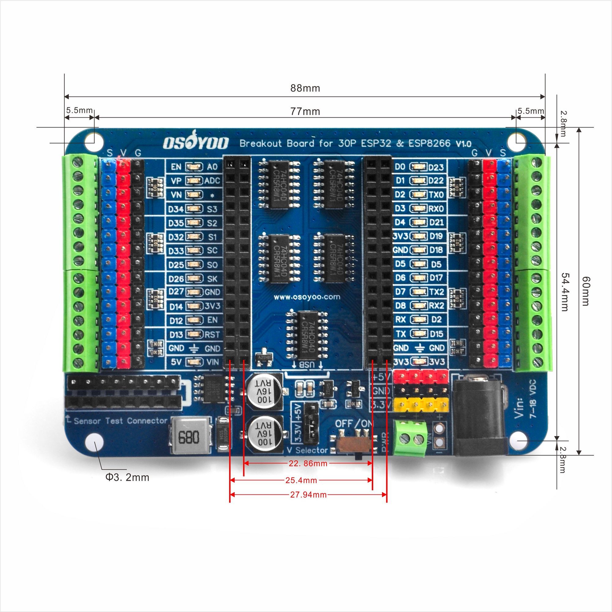
Board dimensions: 88mm x 60mm, Weight: 45g
6. Important Usage Notes
Note 1 — Voltage Selection: Ensure the correct voltage is selected via the V_Selector jumper before connecting devices. The default output is 3.3V. Connecting 5V-only devices without adjusting the jumper, or connecting 3.3V-only devices when set to 5V, may cause permanent damage to your devices.
Note 2 — Power Supply: Do not use the DC barrel jack and the screw terminal power input simultaneously — this may damage the board. When powered via USB only, the V output pin will not supply voltage unless the jumper cap is removed from the V_Selector.
Note 3 — Assembly & Orientation: Ensure the ESP32 / ESP8266 module is correctly oriented and fully seated in the 30-pin connectors before applying power. Incorrect orientation may permanently damage both the module and the breakout board.
Note 4 — Module Sold Separately: The ESP32 / ESP8266 development board is not included. Please purchase your module separately and verify compatibility (chip model, pin count, pin layout) before ordering this breakout board.
7. Resources & Downloads
| File |
Description |
Download |
| Schematic PDF |
Full schematic for 30P ESP32 & ESP8266 Breakout Board |
Download |
| Dimensional Drawing |
Board dimensions with full specifications |
Download |
| ESP32 Arduino Test Code |
GPIO test sketch for ESP32 (ZIP) |
Download |
| ESP8266 Arduino Test Code |
GPIO test sketch for ESP8266 (ZIP) |
Download |
| Fritzing Design File |
30P variant (pending upload) |
Download |
Component Datasheets
| Component |
Description |
Download |
| 74HC04 |
Hex inverter chip driving LED indicators |
Download |
| XL1509 |
DC/DC converter, 5V/2A power output |
Download |
| XK128-2.54MM |
Screw terminal specifications |
Download |


i try the output pins for 5v but it is only 3.3v, i place the v selector on 5v
Are you using onboard USB power or DC power?