Hinweis: Alle OSOYOO Produkte für Arduino sind Drittanbieter-Boards, die voll kompatibel mit Arduino sind.
Autorisierte Online-Händler
Wo kann man das Set mit 18650er Batterien und USB-Ladegerät kaufen
Kaufen von OSOYOO
Kaufen von US
Kaufen von UK
Kaufen von DE
Kaufen von IT
Kaufen von FR
Kaufen von ES
Kaufen von JP
Wo kann man das Set mit 9V und 18650 Batteriegehäusen kaufen
Kaufen von OSOYOO
Kaufen von US
Kaufen von UK
Kaufen von DE
Kaufen von IT
Kaufen von FR
Kaufen von ES
Kaufen von JP
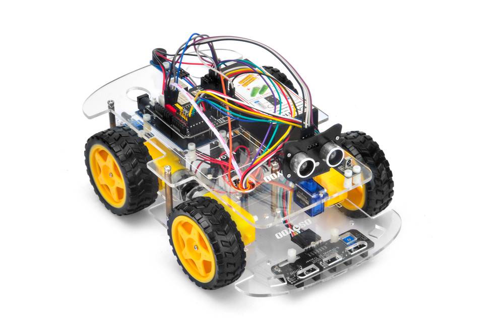
Zielsetzung
In diesem Projekt verbinden wir das Roboterauto mit dem WLAN und verwenden eine App, um das Auto über das Internet zu steuern. Dies ist eine typische Anwendung des Internet der Dinge (IoT).
Du musst Lektion 5 abgeschlossen haben, bevor du mit dieser Lektion fortfährst.
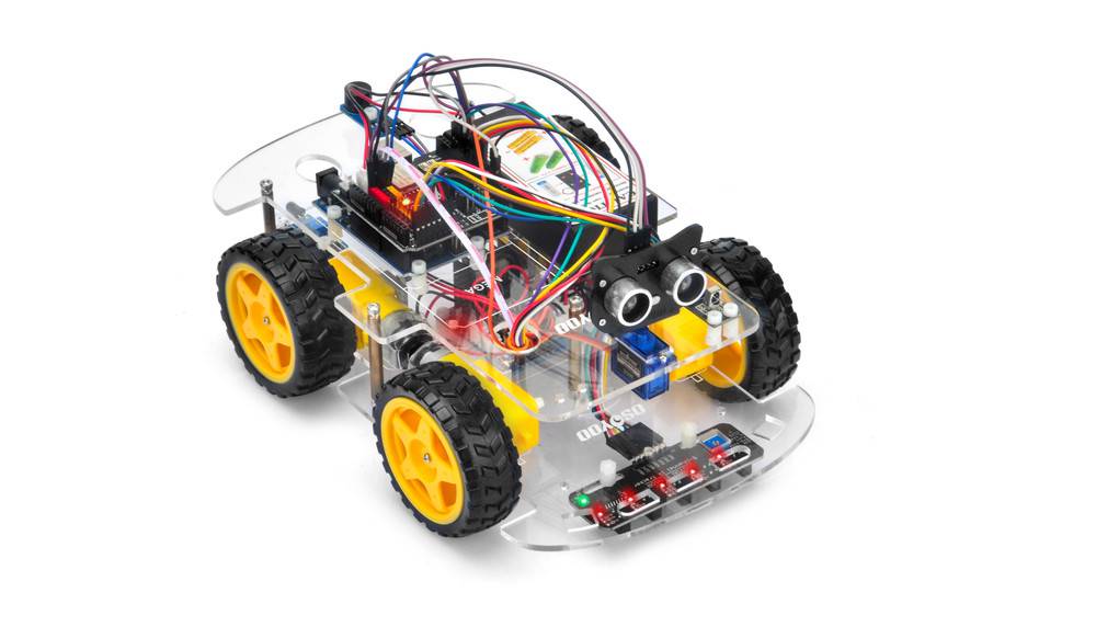
Schritt 1: Baue den Grundrahmen des Smart Cars wie in Lektion 5 beschrieben zusammen. Wenn du den Tracking-Sensor noch nicht installiert hast, schließe zuerst Lektion 4 ab.
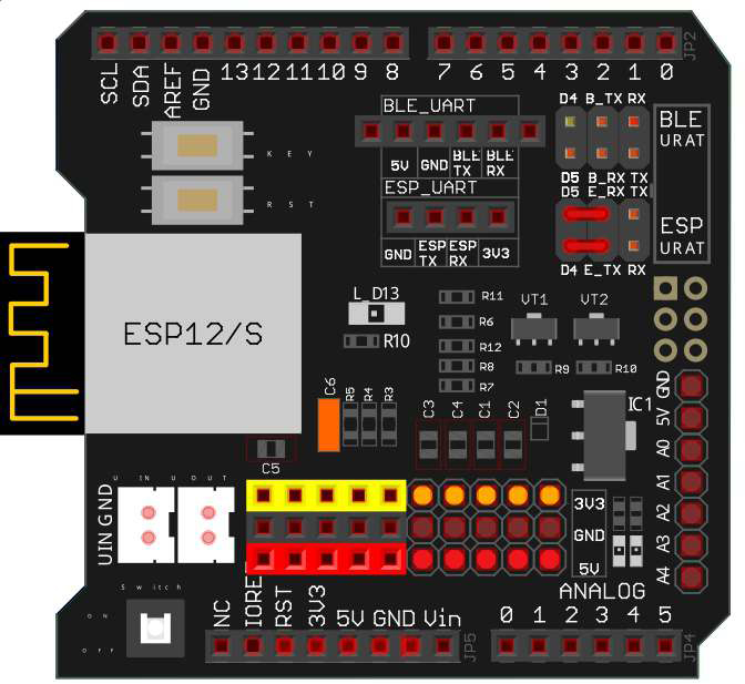
Schritt 2: Verbinde den E_TX (ESP8266 TX)-Pin mit D4 (soft serial RX) und E_RX (ESP8266 RX) mit D5 (soft serial TX) wie im Schaltbild gezeigt
(Hinweis: Standardmäßig sind beim OSOYOO UART WiFi Shield V1.3 die BLE UART TX/RX-Pins über Jumper mit D4/D5 verbunden. Entferne diese Jumper gegebenenfalls und verbinde stattdessen die ESP-Pins korrekt)
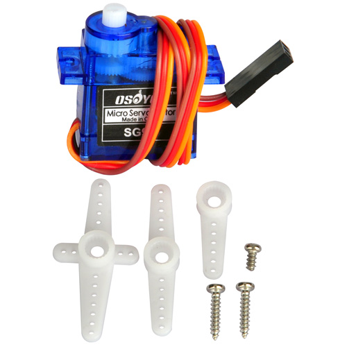
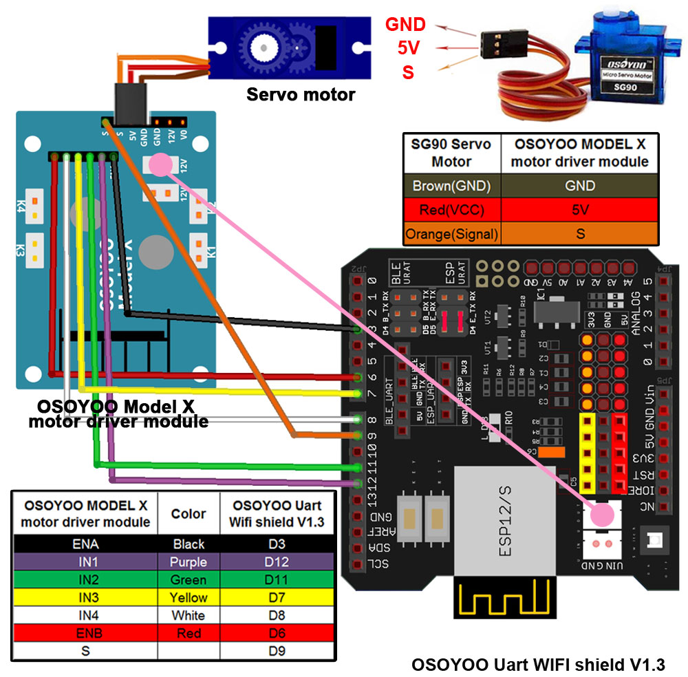
Schritt 3: Verbinde den SG90-Servo-Motor, das OSOYOO MOTOR-Treiber-Modul und das OSOYOO UART WiFi Shield V1.3 entsprechend dem Diagramm:
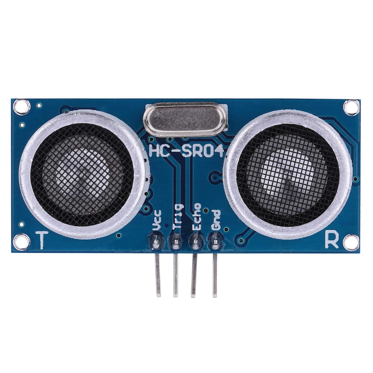
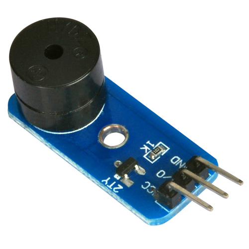
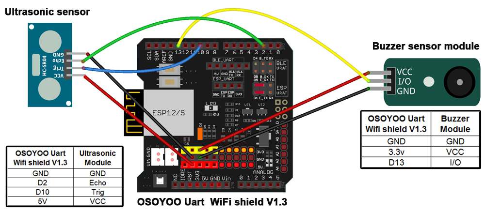
Schritt 4: Verknüpfe das Ultraschall-Modul und das Summer-Modul mit dem WiFi Shield
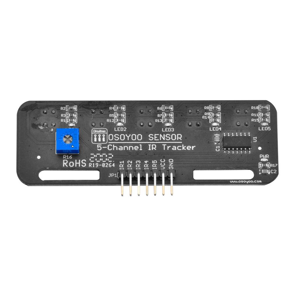
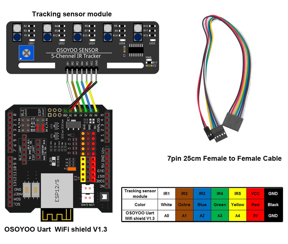
Schritt 5: Schließe den Tracking-Sensor an das WiFi Shield an (wie in Lektion 4)
Note:
1)Bitte denken Sie daran, die Empfindlichkeit der Tracking-Sensormodule gemäß dem Link Lektion 4 einzustellen. 2)Bitte denken Sie daran, die Ausrichtung des Ultraschallsensors wie in Lektion 5beschrieben vorzunehmen
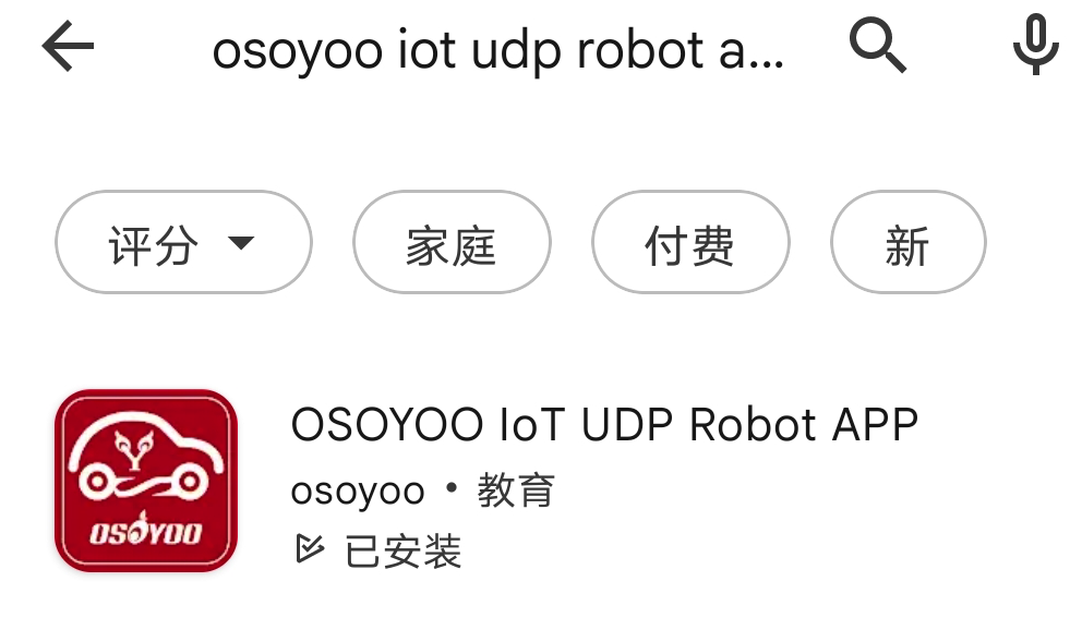
Suche “Osoyoo IoT UDP Robot APP” in
Google Play oder Apple Store
(Wenn Sie diese APP nicht in Google Play finden können, können Sie die APP direkt über den folgenden Link herunterladen: https://osoyoo.com/driver/udp-app.apk)
Schritt 1) App installieren Suche im Google Play Store oder Apple App Store nach der OSOYOO IoT UDP Robot APP und installiere sie.
Falls du die App nicht findest, lade sie direkt von der offiziellen Seite herunter: https://osoyoo.com/driver/udp-app.apk:
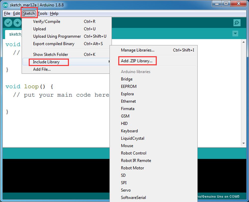
Schritt 2) Bibliothek installieren
Lade das ZIP-Archiv WiFiEsp-master herunter. In der Arduino IDE: Sketch → Include Library → Add .ZIP Library… Wähle die heruntergeladene ZIP-Datei und füge sie dem Projekt hinzu
.
Schritt 3) Sketch-Code Installation
Das V2.1 Roboterauto kann in zwei WLAN-Modi arbeiten:
➡ STA-Modus (WLAN-Client)
➡ AP-Modus (Access Point ohne Internetzugang)
A) STA-Modus Im STA-Modus wird das Roboterauto als Client in einem bestehenden WLAN-Netzwerk betrieben.
Sobald der Sketch läuft, weist der DHCP-Dienst Ihres Routers Ihrem Roboterauto eine IP-Adresse zu, und Ihre APP verwendet diese IP-Adresse für den Zugriff auf Ihr Auto.
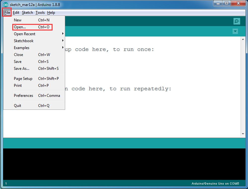
1) Lade den STA-Modus-Sketch v2smartcar-lesson6A herunter und entpacke ihn.
Öffne in der Arduino IDE die Datei v2smartcar-lesson6A.ino und lade sie in dein Board.
2) Ändere im Code folgende Zeilen entsprechend deinem WLAN :
char ssid[] = “YOUR_ROUTER_SSID”; // Dein WLAN-Name
char pass[] = “YOUR_ROUTER_WIFI_PASSWORD”; // Dein WLAN-Passwort
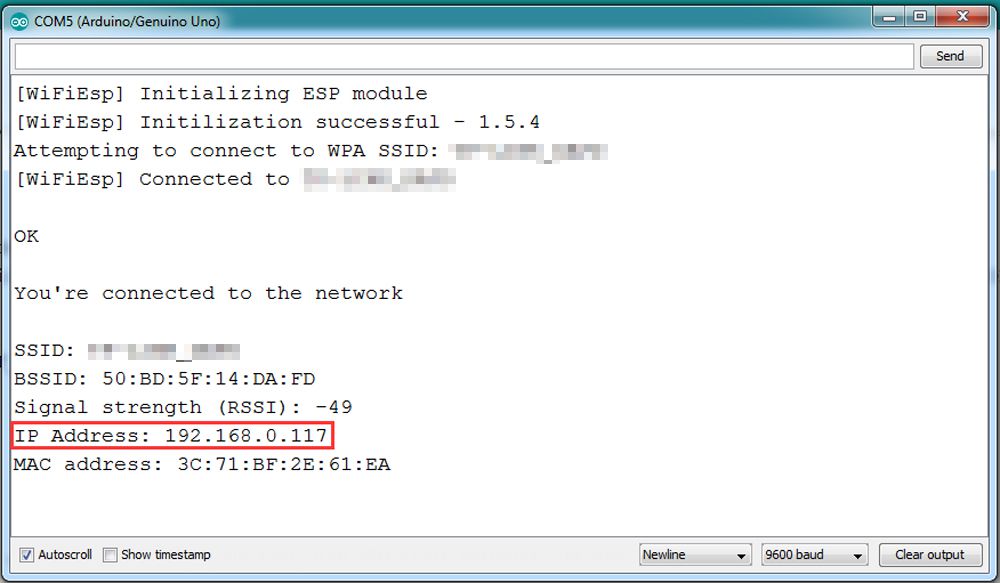
3) Lade den Sketch auf das Board hoch und öffne den Serial Monitor. Dort siehst du die IP-Adresse, die dein Roboterauto vom Router erhalten hat, z. B. 192.168.0.117:
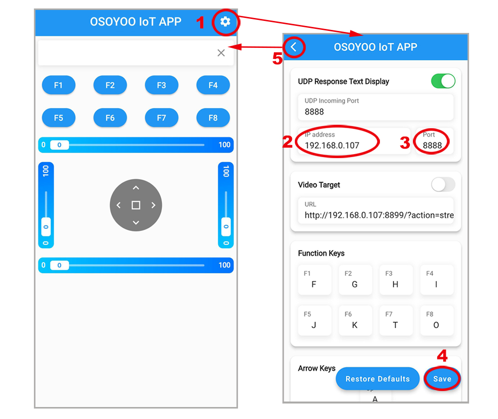
4) Verbinde dein Handy mit demselben WLAN und öffne die App. Gehe in den Einstellungen → gib die IP-Adresse deines Roboters ein → Port 8888 → speichern. Dann zurück zur Steueroberfläche → steuere das Roboterauto.
📌 Wenn du das Auto über das Internet (nicht nur im lokalen Netzwerk) steuern möchtest, musst du in deinem Router Portweiterleitung (Port-Forwarding) einrichten
B)AP-Modus
Wenn kein WLAN-Router vorhanden ist, kann das Roboterauto einen eigenen WLAN-Hotspot bereitstellen.
1) Lade den AP-Modus-Sketch v2smartcar-lesson6B herunter. Entpacke ihn und öffne v2smartcar-lesson6B.ino in der Arduino IDE
2) Lade ihn auf das Board hoch und öffne den Serial Monitor. Dort erscheint ein Netzwerk-SSID osoyoo_robot mit der IP-Adresse 192.168.4.1.
3) Verbinde dein Handy mit dem WLAN osoyoo_robot, öffne die App und stelle als IP 192.168.4.1 und Port 8888 ein. Nun kannst du das Roboterauto steuern.
Abschließende Prüfung:
Schalte das Auto ein.
Öffne die App → klicke Settings → IP-Adresse korrekt einstellen.
➤ STA-Modus: Handy und Roboter im gleichen WLAN.
➤ AP-Modus: Verbunden mit dem Hotspot osoyoo_robot.
📱 Jetzt kannst du mit den Tasten ◄ ► ▲ ▼ das Auto fahren und mit || (Pause) stoppen.
➡ Wenn du F8, fährt das Auto autonom wie in Lektion 5.
➡ Wenn du F7, fährt es der Linie nach wie in Lektion 4.
Hinweis: F1~F6 sind weitere Entwicklungsfunktionen für die Zukunft.
FAQ über die WIFI UDP APP und den Sketch Code:
Q1)Wie man die Geschwindigkeit des Roboterautos einstellt? A: Um die Fahrgeschwindigkeit zu ändern, bearbeite im Code die Werte in den Zeilen etwa bei:
Q 2)Was passiert, wenn Sie Tasten in OSOYOO WiFi UDP Robot Car APP drücken ? A: Wenn Sie eine Taste der APP drücken, sendet die APP eine Nachricht mit einem Buchstaben über das UDP-Protokoll an das Zielgerät (in diesem Beispiel unser WIFI Shield)
Button
UDP message
F1
F
F2
G
F3
H
F4
I
F5
J
F6
K
▲
A
▼
B
►
R
◄
L
square
E
F7
O
F8
T
Q3)Wie behandelt die Karte den UDP-Befehl?
Die folgenden switch(c)-Anweisungen in der Sketchnote v2smartcar-lesson6 behandeln den UDP-Befehl
            switch (c)    //serial control instructions
            {

               case 'A':Drive_Status=MANUAL_DRIVE; Drive_Num=GO_ADVANCE;  WorkMode="GO_ADVANCE";break;
               case 'L':Drive_Status=MANUAL_DRIVE; Drive_Num=GO_LEFT; WorkMode="GO_LEFT";break;
               case 'R':Drive_Status=MANUAL_DRIVE; Drive_Num=GO_RIGHT;WorkMode="GO_RIGHT";break;
               case 'B':Drive_Status=MANUAL_DRIVE; Drive_Num=GO_BACK;WorkMode="GO_BACK";break;
               case 'E':Drive_Status=MANUAL_DRIVE; Drive_Num=STOP_STOP;WorkMode="STOP_STOP";break;
               case 'O':Drive_Status=AUTO_DRIVE_UO;Serial.println("go OBSTACLE");WorkMode="OBSTACLE";break;
               case 'T':Drive_Status=AUTO_DRIVE_LF;WorkMode="line follow";break;
               case 'G':track_speed=track_speed+10;
                        if(track_speed>200) track_speed=200
                         ;break;
               case 'J':track_speed=track_speed-10;
                        if(track_speed<80) track_speed=80
                         ;break;
               default:break;
              } //END OF ACTION SWITCH
Im obigen Code, c in den switch() die von der APP des Mobiltelefons gesendeten UDP-Daten. Sobald die Taste APP ▲ gedrückt wird, wird die Zeile case ‘A’ … den Befehl verarbeiten und das Auto vorwärts fahren lassen.
I am trying to use the first version of the WIFI code (STA Mode). I got the code to compile and load into the robot, however, I am getting an error stating -Cannot initialize ESP module, WIFI Shield is not present.
1. Please confirm that connect E_TX (Esp8266 TX) pin to Arduino D4(UNO soft serial RX) and E_RX(ESP8266_RX) pin to D5(UNO software serial TX) as the step 2 in the installation
2. Please check that you change the ssid and psw to your own before uploading the code.
3. Please confirm that the voltage is more than 7.2V.
Still waiting on answer to my question for Lesson 5. So now I have moved on to Lesson 6A. All connections made and sketch installed in board. I have entered my router ssid and password into sketch. I have chosen STA mode. When I open the serial monitor I get the following message. “W[WIFIESP} Initializing ESP Module”
“WiFi ESP TIMEOUT” “cannot initialize ESP module” “WiFi Shield not present” . I have checked the router but it does not show the Shield as a connected device. Can you help? I have both 5G and 2.4G available.
Regards, Jim Robb
I have moved on to Lesson 6A. All connections made and sketch installed in board. I have entered my router ssid and password into sketch. I have chosen STA mode. When I open the serial monitor I get the following message. “W[WIFIESP} Initializing ESP Module, W[WiFiESP] Initilization successful, W[WiFiESP] Attempting to connect to [ssid] , w[WiFiESP] failed connecting to [ssid]. etc ——-
The router does not show the Shield as a connected device. Can you help? I have both 5G and 2.4G available.
Regards, Jim Robb
based on your description, you are very very very very likely to have written wrong SSID or PASSWORD in the sketch code. Please double check every letter of your SSID and password in the code include space and everything. Also make sure your robot car is connecting to a wifi router, not to a cell phone hotspot. Cell phone hotspot might block ESP8266 as STA client.
Hi,
You were correct I had missed out one of the letters in the password. The print is so small my old eyes are not so good for that.
Many thanks for your help.
Regards, Jim.
when I try to sketch lesson 6 I get the following error message
C:\Users\Steve\Desktop\v2smartcar-lesson6A\v2smartcar-lesson6A.ino:11:10: fatal error: WiFiEspUdp.h: No such file or directory
#include
^~~~~~~~~~~~~~
compilation terminated.
exit status 1
Compilation error: WiFiEspUdp.h: No such file or directory
Did I miss something?
I redownloaded the first set and sketched it now I’m getting
[WiFiEsp] >>> TIMEOUT >>>
[WiFiEsp] >>> TIMEOUT >>>
[WiFiEsp] >>> TIMEOUT >>>
[WiFiEsp] >>> TIMEOUT >>>
[WiFiEsp] Cannot initialize ESP module
[WiFiEsp] >>> TIMEOUT >>>
[WiFiEsp] No tag found
WiFi shield not present
1. Please confirm that connect E_TX (Esp8266 TX) pin to Arduino D4(UNO soft serial RX) and E_RX(ESP8266_RX) pin to D5(UNO software serial TX) as the step 2 in the installation
2. Please check that you change the ssid and psw to your own before uploading the code.
You need change the code Line 96 and Line 98 :
char ssid[] = “YOUR_ROUTER_SSID”; // replace this with your router wifi SSID
char pass[] = “YOUR_ROUTER_WIFI_PASSWORD”; // replace with your wifi password
3. Please confirm that the voltage is more than 7.2V.
I have uploaded this sketch ok. However how can I see the debug output in the Serial Monitor ?
When connected via a USB cable the serial monitor shows output. However, as soon as the car is untethered the connection is lost.
When connected the monitor say to open a browser window, which is where I assume I will see the monitor, however, the browser does not find a page at the location stated.
9:48:21.699 -> [WiFiEsp] Initializing ESP module
09:48:26.458 -> [WiFiEsp] Initilization successful – 1.5.4
09:48:26.525 -> Attempting to connect to WPA SSID: BT-XXXXXX
09:48:31.543 -> [WiFiEsp] Connected to BT-XXXXX
09:48:31.607 -> You’re connected to the network
09:48:31.642 ->
09:48:31.642 -> IP Address: 192.168.1.220
09:48:31.677 ->
09:48:31.677 -> To see this page in action, connect to BT-6MA89Q and open a browser to http://192.168.1.220
09:48:31.772 ->
09:48:31.772 -> Listening on port 8888
I’m running into the same problem that many others seem to have hit. I can’t get the wifi module to connect at all. I’ve swapped two different UNOs, two different Mega2560s, and all the wiring I can. I have the Arduino powered from a 12V wall wart (I had everything on the robot, but pulled it apart to make sure that wasn’t the issue).
The code stops running after the WiFi.init call returns with a WL_NO_SHIELD value, so this isn’t an issue with the network settings. I’ve even tried the network scanner example from the wifi library to see if that might be an issue.
On the UNO I leave the jumpers in place across D4/E_TX and D5/E_RX. On the 2560 I’ve various pairings of E_RX/D1[89] and E_TX/D1[89]. I’m stuck here. Do I have a bad board or is there more testing I can do?
Ok, got thru the first part. The shield starts out at 115200bps and without that there’s no communication. Now I can get the shield connected to my local wifi. But, the part that says connect a browser to http://addr:8888 doesn’t work. Shouldn’t the shield be using TCP here? I can see the device on my local network.
11:30:34:179 -> [WiFiEsp] Connected to xxxxx
11:30:34:215 -> You’re connected to the network
11:30:34:251 ->
11:30:34:251 -> IP Address: 192.168.54.36
11:30:34:280 -> 3C:E9:0E:E5:4D:44
11:30:34:301 ->
11:30:34:301 -> To see this page in action, connect to xxxxx and open a browser to http://192.168.54.36:8888
11:30:34:407 -> Listening on port 8888


I am trying to use the first version of the WIFI code (STA Mode). I got the code to compile and load into the robot, however, I am getting an error stating -Cannot initialize ESP module, WIFI Shield is not present.
1. Please confirm that connect E_TX (Esp8266 TX) pin to Arduino D4(UNO soft serial RX) and E_RX(ESP8266_RX) pin to D5(UNO software serial TX) as the step 2 in the installation
2. Please check that you change the ssid and psw to your own before uploading the code.
3. Please confirm that the voltage is more than 7.2V.
Still waiting on answer to my question for Lesson 5. So now I have moved on to Lesson 6A. All connections made and sketch installed in board. I have entered my router ssid and password into sketch. I have chosen STA mode. When I open the serial monitor I get the following message. “W[WIFIESP} Initializing ESP Module”
“WiFi ESP TIMEOUT” “cannot initialize ESP module” “WiFi Shield not present” . I have checked the router but it does not show the Shield as a connected device. Can you help? I have both 5G and 2.4G available.
Regards, Jim Robb
I have moved on to Lesson 6A. All connections made and sketch installed in board. I have entered my router ssid and password into sketch. I have chosen STA mode. When I open the serial monitor I get the following message. “W[WIFIESP} Initializing ESP Module, W[WiFiESP] Initilization successful, W[WiFiESP] Attempting to connect to [ssid] , w[WiFiESP] failed connecting to [ssid]. etc ——-
The router does not show the Shield as a connected device. Can you help? I have both 5G and 2.4G available.
Regards, Jim Robb
I refer to my question of December 13th at 9.16pm. Have you any suggestions why my Shield will not connect to my WiFi ESP?
Regards, Jim Robb
hi, James Robb,
based on your description, you are very very very very likely to have written wrong SSID or PASSWORD in the sketch code. Please double check every letter of your SSID and password in the code include space and everything. Also make sure your robot car is connecting to a wifi router, not to a cell phone hotspot. Cell phone hotspot might block ESP8266 as STA client.
Hi,
You were correct I had missed out one of the letters in the password. The print is so small my old eyes are not so good for that.
Many thanks for your help.
Regards, Jim.
when I try to sketch lesson 6 I get the following error message
C:\Users\Steve\Desktop\v2smartcar-lesson6A\v2smartcar-lesson6A.ino:11:10: fatal error: WiFiEspUdp.h: No such file or directory
#include
^~~~~~~~~~~~~~
compilation terminated.
exit status 1
Compilation error: WiFiEspUdp.h: No such file or directory
Did I miss something?
I redownloaded the first set and sketched it now I’m getting
[WiFiEsp] >>> TIMEOUT >>>
[WiFiEsp] >>> TIMEOUT >>>
[WiFiEsp] >>> TIMEOUT >>>
[WiFiEsp] >>> TIMEOUT >>>
[WiFiEsp] Cannot initialize ESP module
[WiFiEsp] >>> TIMEOUT >>>
[WiFiEsp] No tag found
WiFi shield not present
1. Please confirm that connect E_TX (Esp8266 TX) pin to Arduino D4(UNO soft serial RX) and E_RX(ESP8266_RX) pin to D5(UNO software serial TX) as the step 2 in the installation
2. Please check that you change the ssid and psw to your own before uploading the code.
You need change the code Line 96 and Line 98 :
char ssid[] = “YOUR_ROUTER_SSID”; // replace this with your router wifi SSID
char pass[] = “YOUR_ROUTER_WIFI_PASSWORD”; // replace with your wifi password
3. Please confirm that the voltage is more than 7.2V.
I have uploaded this sketch ok. However how can I see the debug output in the Serial Monitor ?
When connected via a USB cable the serial monitor shows output. However, as soon as the car is untethered the connection is lost.
When connected the monitor say to open a browser window, which is where I assume I will see the monitor, however, the browser does not find a page at the location stated.
9:48:21.699 -> [WiFiEsp] Initializing ESP module
09:48:26.458 -> [WiFiEsp] Initilization successful – 1.5.4
09:48:26.525 -> Attempting to connect to WPA SSID: BT-XXXXXX
09:48:31.543 -> [WiFiEsp] Connected to BT-XXXXX
09:48:31.607 -> You’re connected to the network
09:48:31.642 ->
09:48:31.642 -> IP Address: 192.168.1.220
09:48:31.677 ->
09:48:31.677 -> To see this page in action, connect to BT-6MA89Q and open a browser to http://192.168.1.220
09:48:31.772 ->
09:48:31.772 -> Listening on port 8888
This web address just doesn’t load http://192.168.1.220 – Any Ideas ?
I’m running into the same problem that many others seem to have hit. I can’t get the wifi module to connect at all. I’ve swapped two different UNOs, two different Mega2560s, and all the wiring I can. I have the Arduino powered from a 12V wall wart (I had everything on the robot, but pulled it apart to make sure that wasn’t the issue).
The code stops running after the WiFi.init call returns with a WL_NO_SHIELD value, so this isn’t an issue with the network settings. I’ve even tried the network scanner example from the wifi library to see if that might be an issue.
On the UNO I leave the jumpers in place across D4/E_TX and D5/E_RX. On the 2560 I’ve various pairings of E_RX/D1[89] and E_TX/D1[89]. I’m stuck here. Do I have a bad board or is there more testing I can do?
[WiFiEsp] Initializing ESP module
[WiFiEsp] >>> TIMEOUT >>>
[WiFiEsp] >>> TIMEOUT >>>
[WiFiEsp] >>> TIMEOUT >>>
[WiFiEsp] >>> TIMEOUT >>>
[WiFiEsp] >>> TIMEOUT >>>
[WiFiEsp] Cannot initialize ESP module
[WiFiEsp] >>> TIMEOUT >>>
[WiFiEsp] No tag found
WiFi shield not present
Ok, got thru the first part. The shield starts out at 115200bps and without that there’s no communication. Now I can get the shield connected to my local wifi. But, the part that says connect a browser to http://addr:8888 doesn’t work. Shouldn’t the shield be using TCP here? I can see the device on my local network.
11:30:34:179 -> [WiFiEsp] Connected to xxxxx
11:30:34:215 -> You’re connected to the network
11:30:34:251 ->
11:30:34:251 -> IP Address: 192.168.54.36
11:30:34:280 -> 3C:E9:0E:E5:4D:44
11:30:34:301 ->
11:30:34:301 -> To see this page in action, connect to xxxxx and open a browser to http://192.168.54.36:8888
11:30:34:407 -> Listening on port 8888
Do you have a model for App inventor as a guide
what kind of model do you need?please email to [email protected]
Eu gostaria de replicar a app, mas estou com dificuldades. Criaram a app com o MIT Inventor; se sim, como?
Sorry, we don’t know the reason why you want to copy this APP?